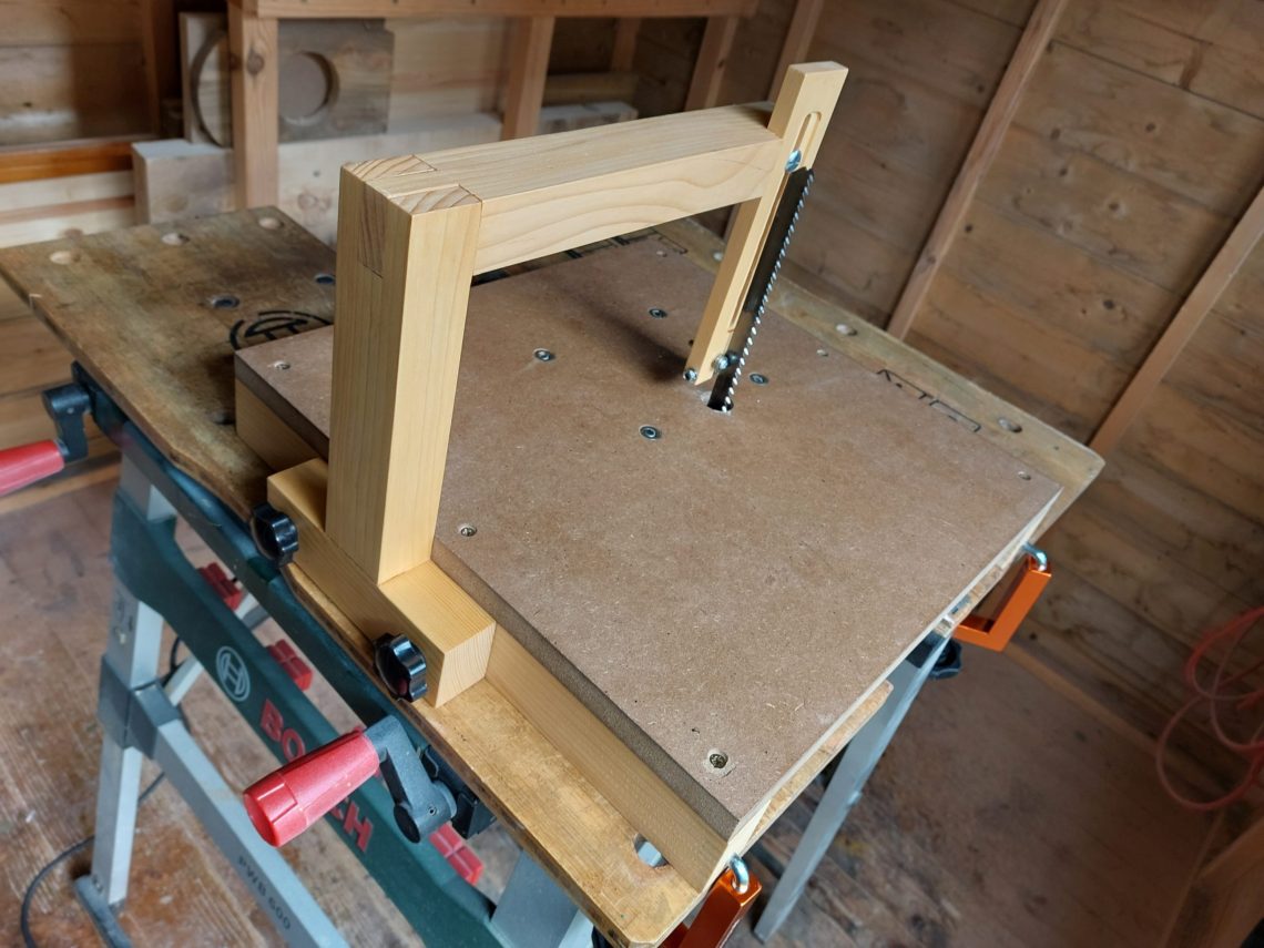
Jigsaw table with blade guide
This jig is mounted to a workbench with two fence clamps, its top is made of MDF, the arm is wooden, and the blade is guided by three bearings. The range of blades that can be used with this jig starts with short ones – used without the arm – and ends with massive ones – perfect for resawing. For most of my woodworking needs only two longer blades have been designated to use with it – the 178mm and 250mm ones (7 and 10 inches long, T744D and T1044DP). They have different depths, the shorter one is also slicker – perfect for cutting curves and the longer one is heavier in build- suitable for straight cuts. The jig is easy to store, can be quickly disassembled, and is not too heavy. Even though it’s just a jig, it features glued woodworking joints and is finished with a few coats of hard wax oil.


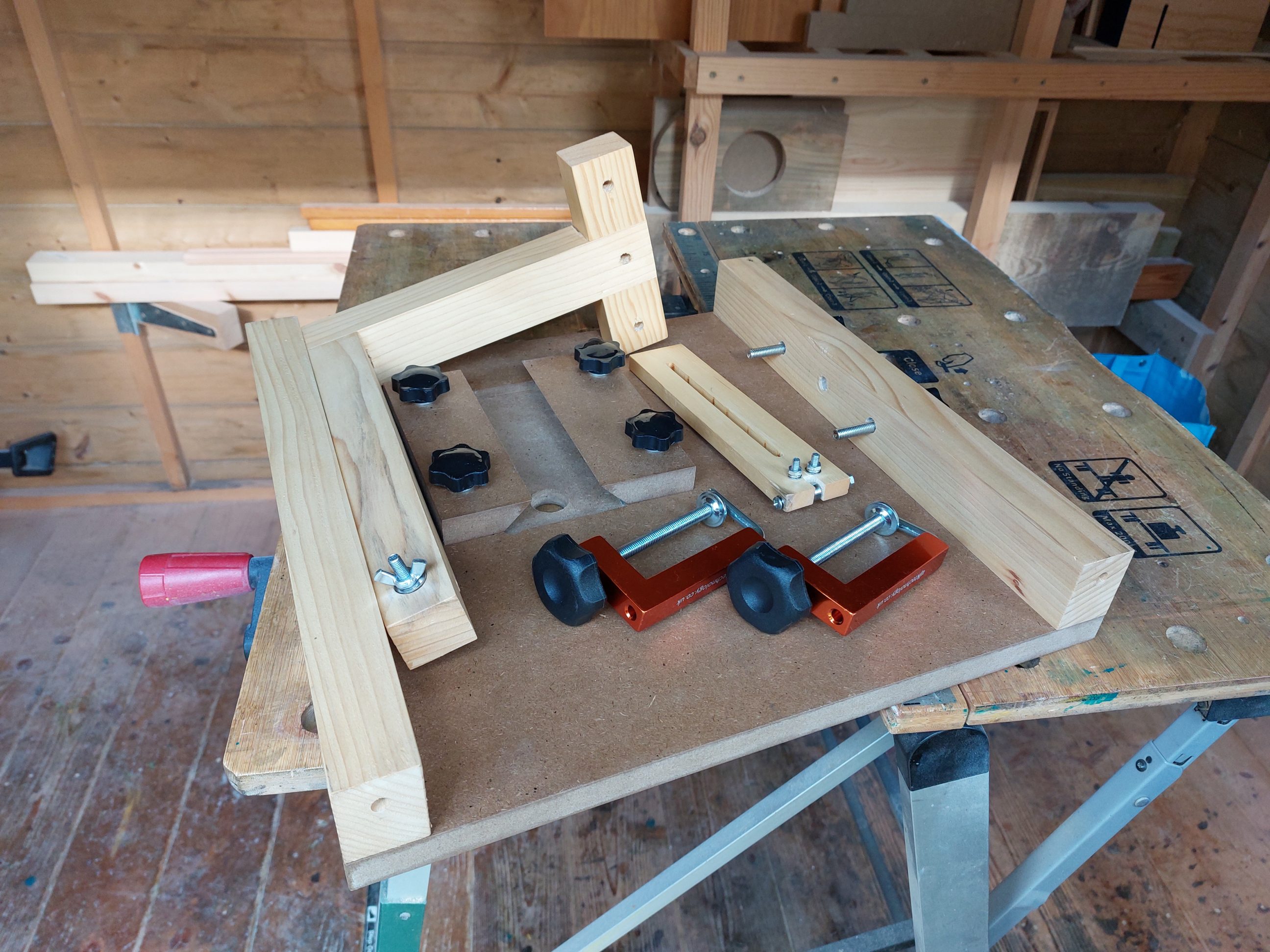
I started by cutting the base, using a 19 mm sheet of MDF. The size I chose for it was 400 x 400 mm (15 3/4 x 15 3/4 inches). Then, I cut a pair of holding blocks with one edge square and the other at a 45º angle. Next, I traced out the jigsaw base plate and used my router to cut out the recess, adjusting the bit depth as needed.


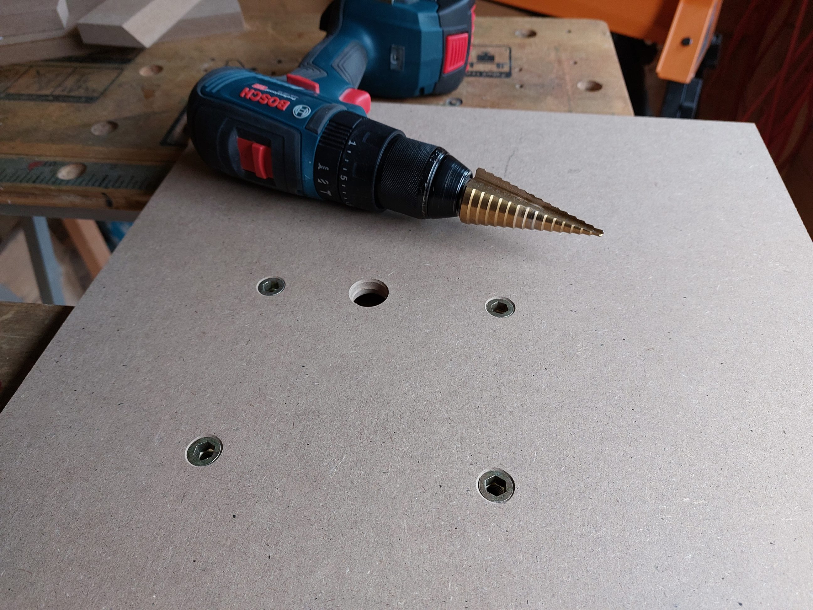
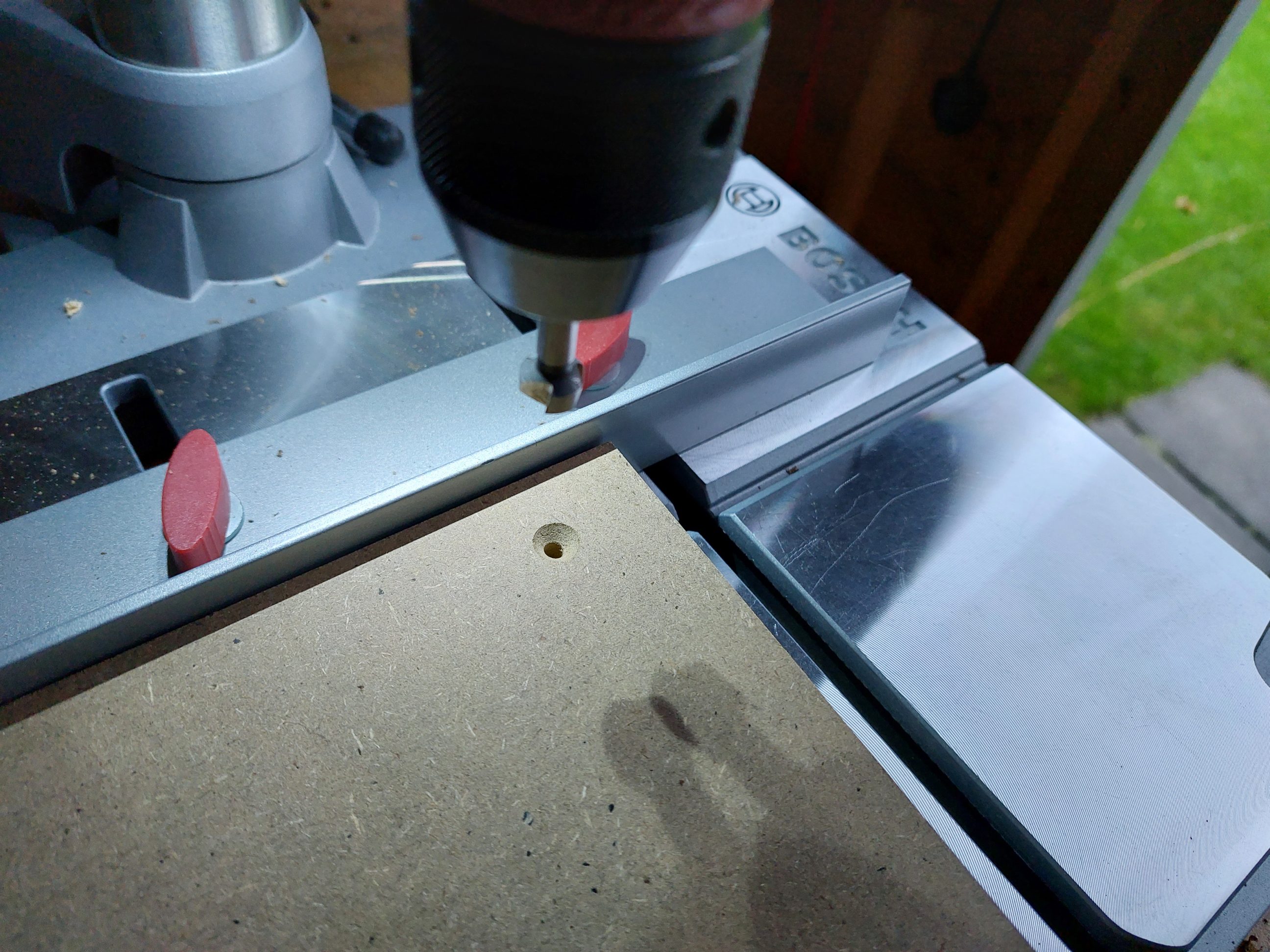
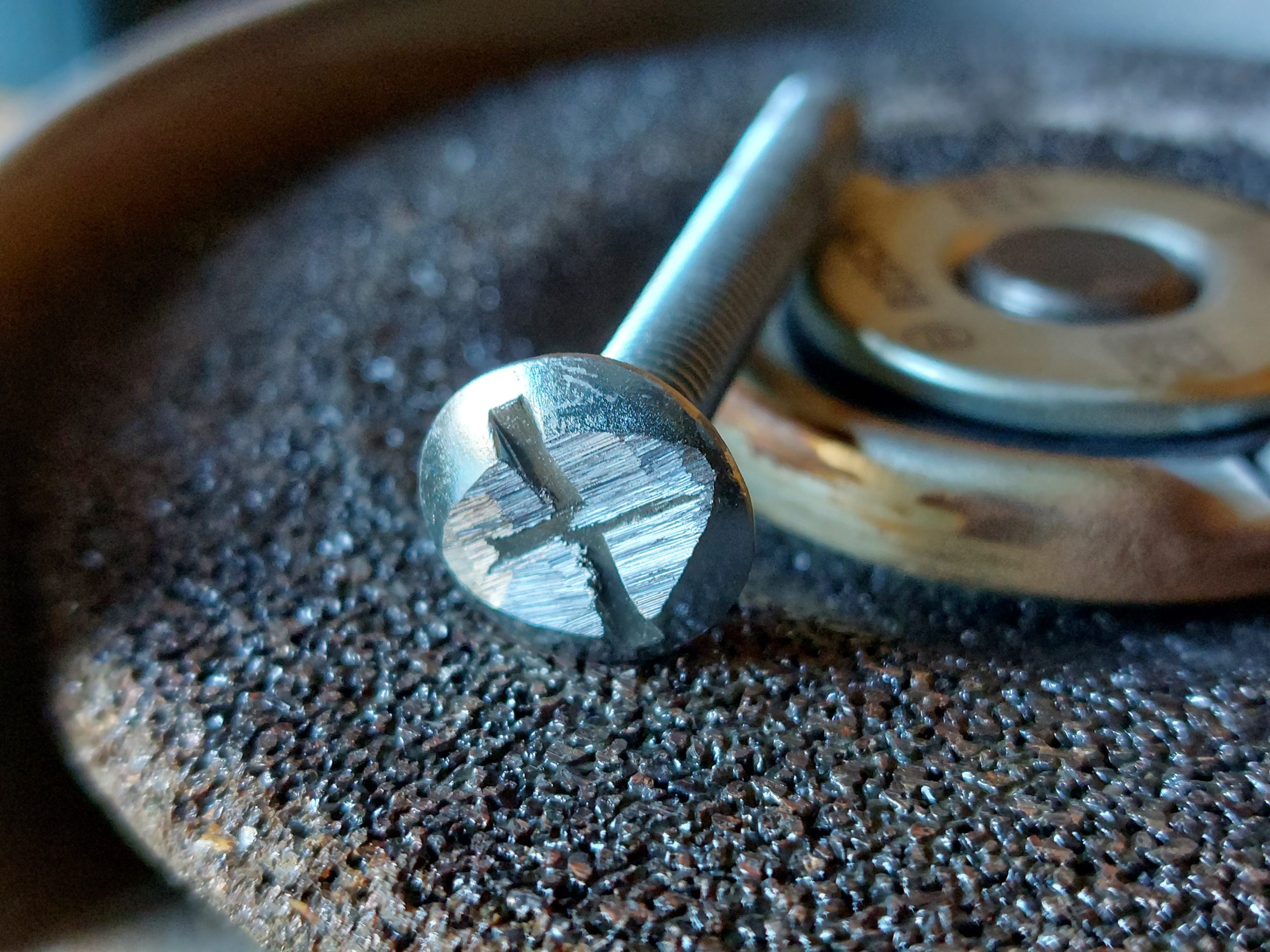
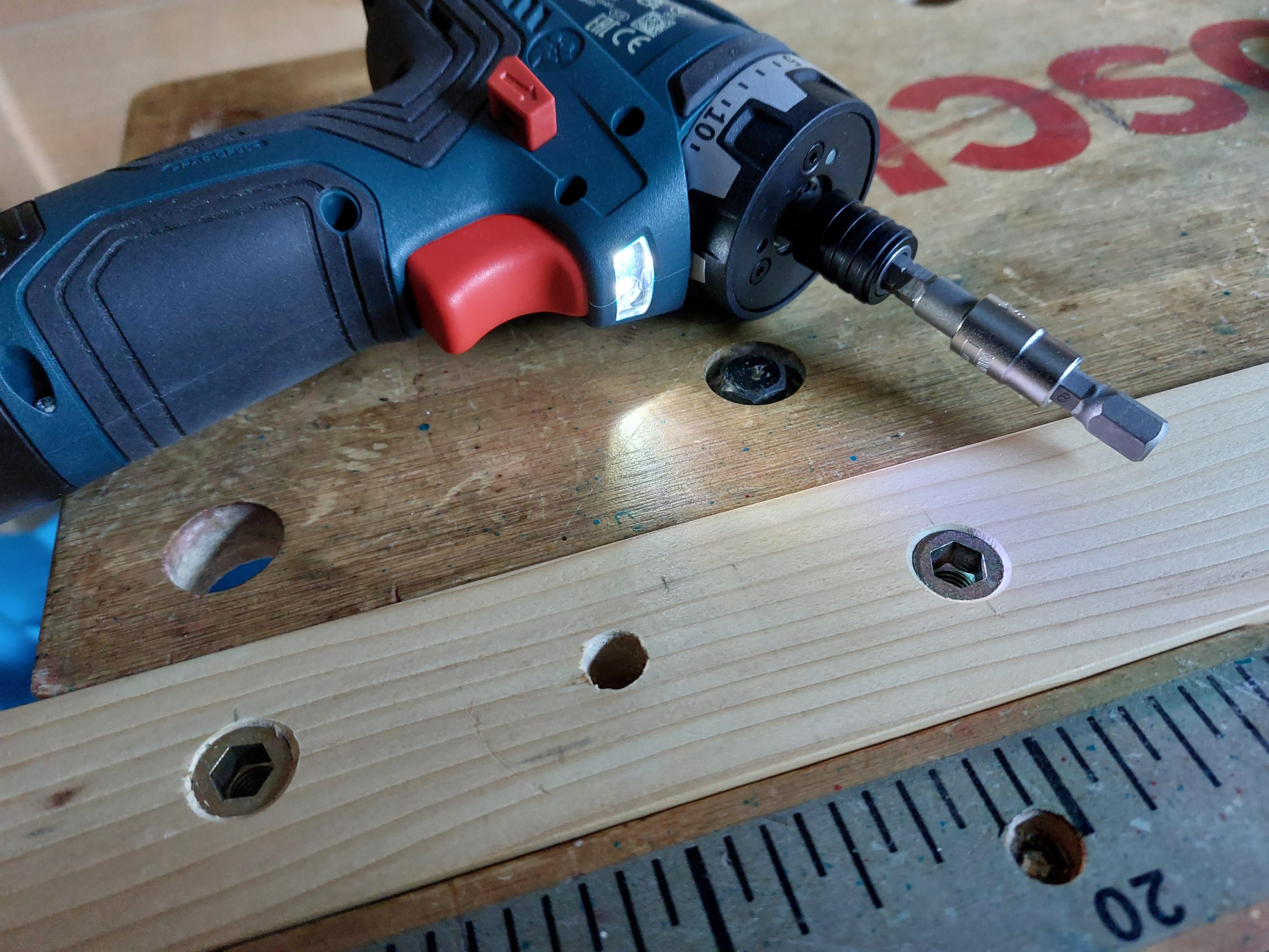
The threaded inserts I purchased were too long for the application, so I had to grind them down to the desired length. To test which type of wood bit would work best, I first used a scrap piece of MDF. I found that regular HSS bits worked well and did not cause any blow-outs, even without scrap wood supporting the MDF sheet from the back side. To start the drilling process, I first used a centre punch to make dimples. I then heavily countersunk the top edges to ensure that the inserts would sit just below the surface.


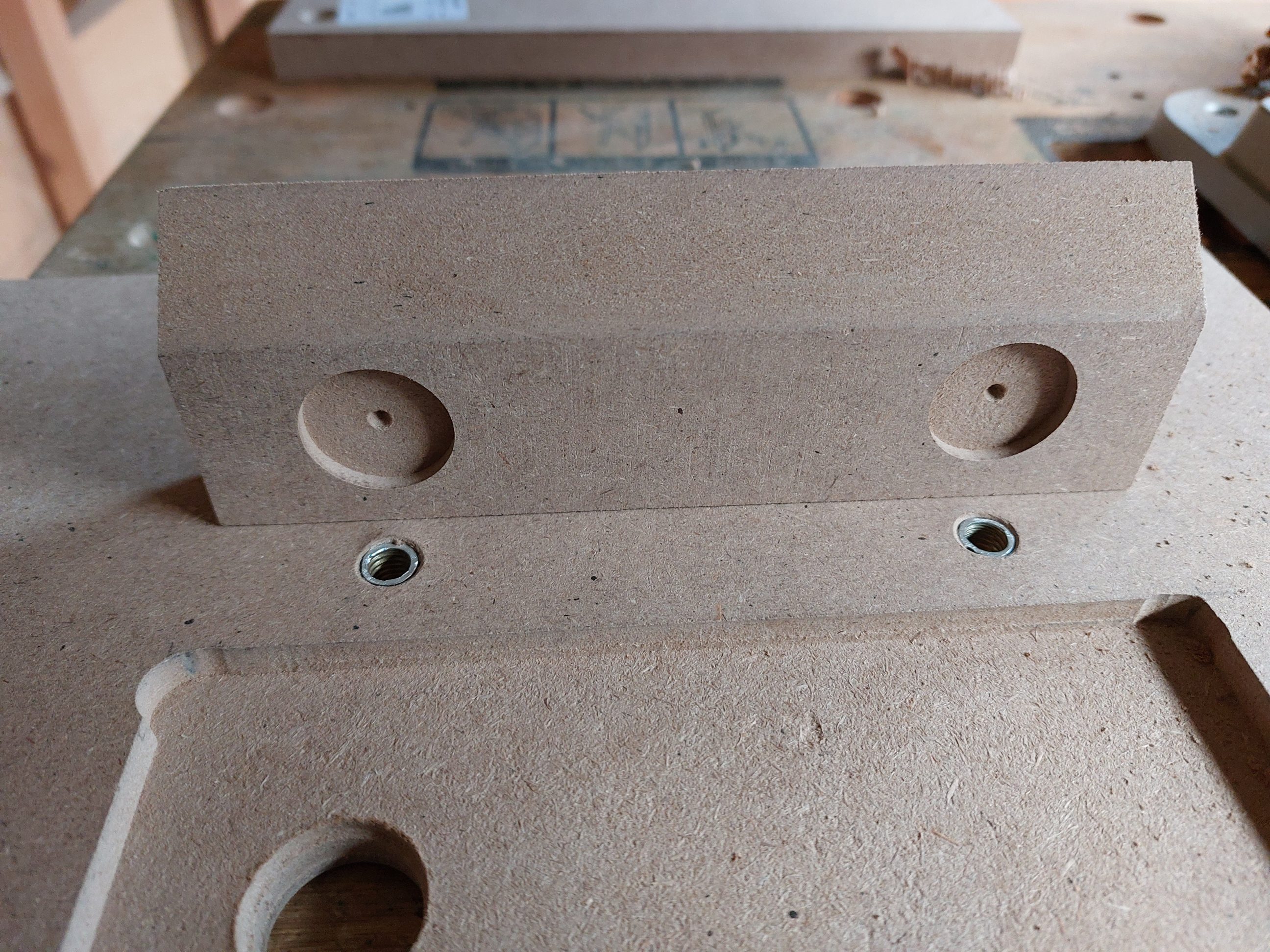
To drill the blade hole, I initially used a Forstner bit, but I completed the task with a step bit, which automatically countersunk the edges – an unexpected bonus. When I screwed in the threaded inserts, they pushed some MDF material out at the back and deformed the flat surface. Although I could have sanded it flush with the rest, I chose a more complex solution. I drilled shallow nests in clamping blocks, which allowed them to sit perfectly flat and tight against the main board. To create wiggle room for the 8mm bolts, I drilled 10mm holes and countersunk them from both sides, as I did with everything in the project.


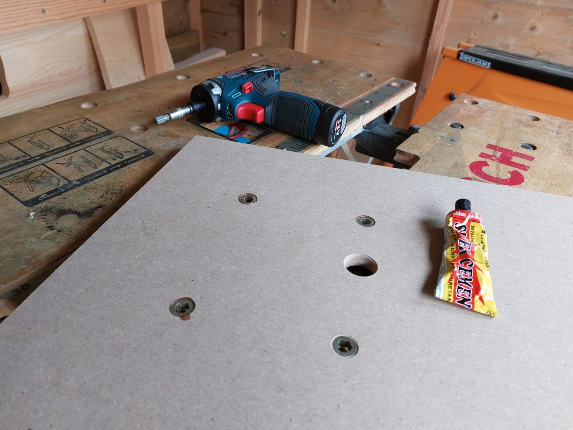
There was a minor flaw in the design – tightening the bolts clockwise theoretically forced the inserts to spin counterclockwise, To prevent this from happening, I applied polyurethane glue in the next step to permanently bond the MDF and the threads together. That supposedly should hold forever, but just in case a “Do Not Overtighten Screws” sticker could be placed next to it, as a reminder.
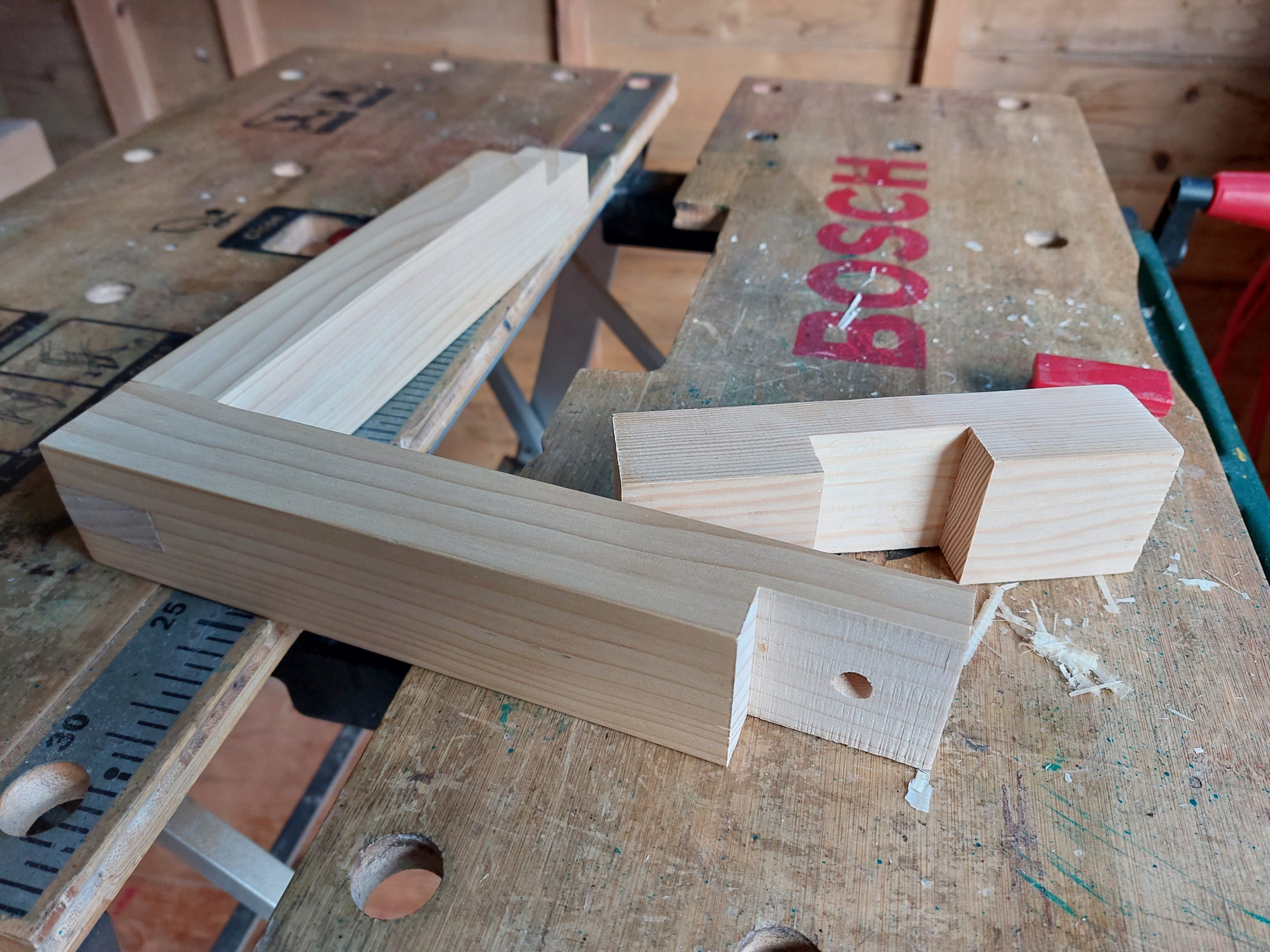
I continued with the project and began building the arm. I used my table saw to rip-cut and resaw some timber, and then planed it down in the next step with my thickness planer. To reduce the cost of the project, I used off-cuts and scraps, but finished with a bunch of short, but long enough, slats and strips.


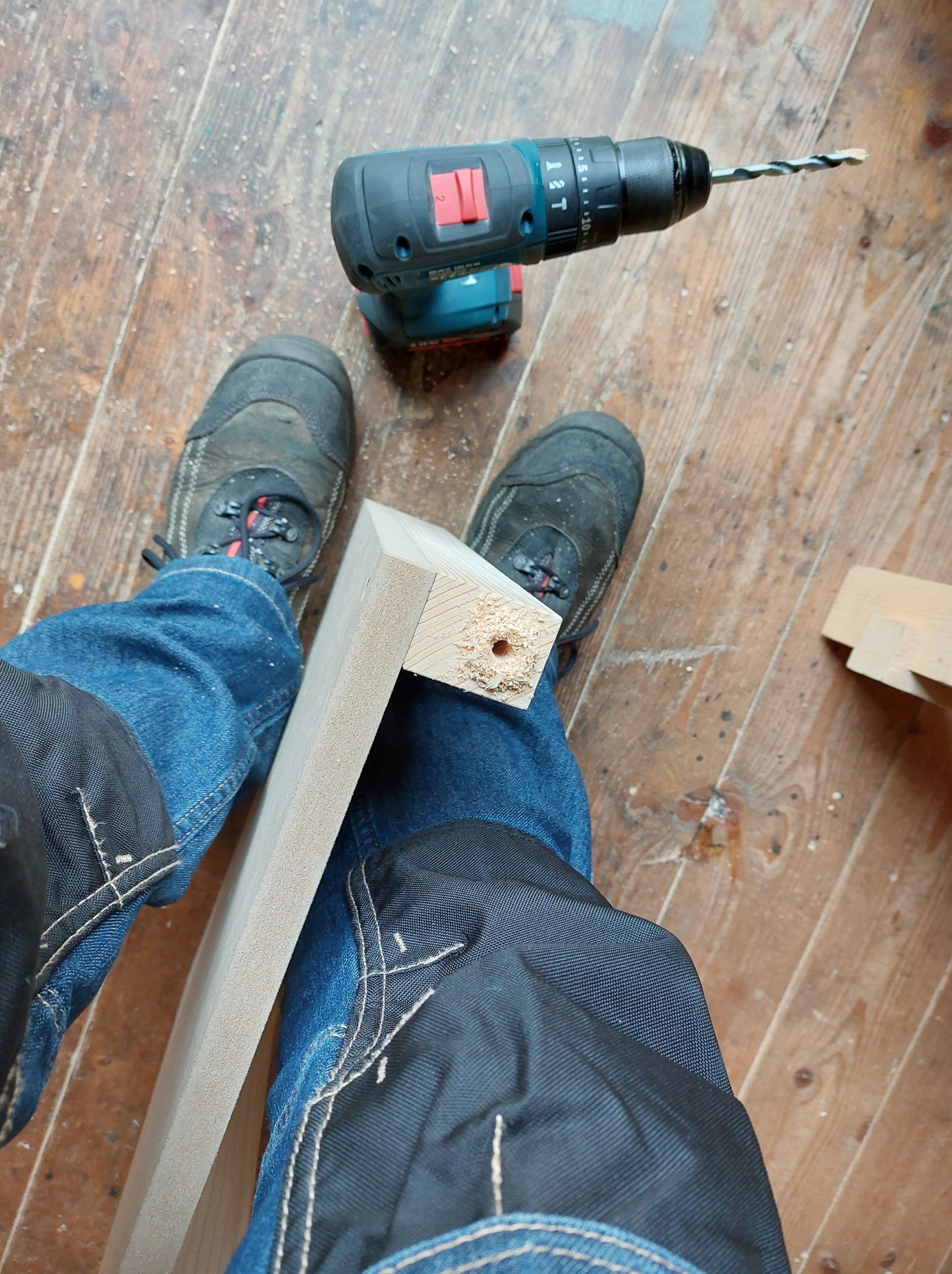
The mitre gauge fence was adjusted and I used it for cutting mortises. I also cut tenons, but with the workpiece laid flat. Any fine adjustments were cut with a chisel. Both upright parts of the arm were still too long and they were trimmed down in the next step.


Using my drill press, I drilled, counterbored and countersank all the holes I needed for the bolts. The single hole drilled in the base, the initial design, was slightly bigger than the corresponding bolt to allow the arm to be micro-adjusted back and forth. It was replaced with 2 mounting points later on, but the same idea of 1 – 2 mm play was applied again, by drilling oversized holes. Everything it needed for a perfect alignment was that tiny wiggle room.


I clamped my router upside-down to the workbench and used it to cut the channel on the top piece. It took me 2 attempts, and unfortunately, I lost the original piece, which was the same species as the rest. I had to make it again, using a different and only available piece of timber I had on hand. Although it was different from the rest, I chose to prioritize functionality over aesthetics for a jig. Next, I attached the MDF top to the rails with screws that would not interfere with the holes drilled in the following step. They were two 7 mm holes for fence clamps to hold the jig down. Finally, I glued up the bridle joint and finished for the day.


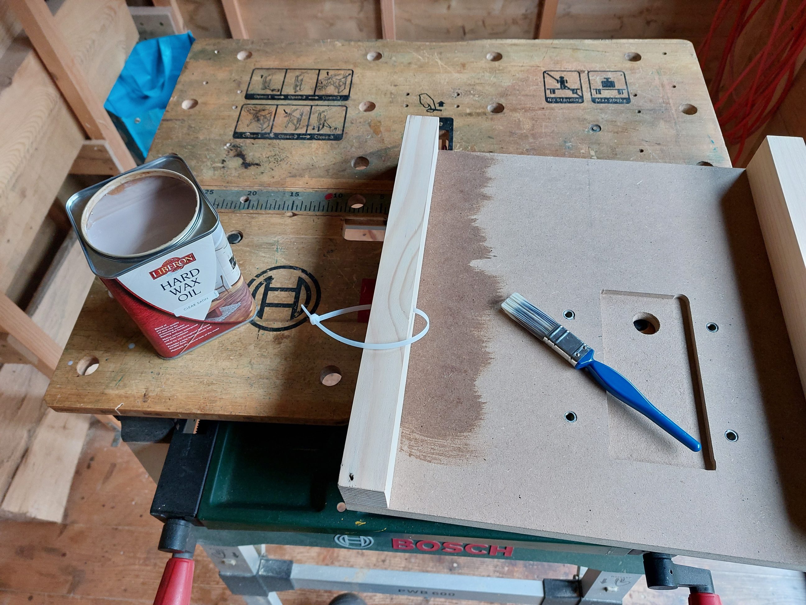
Once the arm was cleaned up and sanded, I applied the first coat of hard wax oil using a brush and allowed it to dry before applying the final coat. This “oil” is more like a water-based varnish that has always been a perfect choice for MDF, at least for me. They both seal and prime the surface, making it splash and scratch-resistant. I hoped that the new product would do the same job and there were no surprises – it worked well. I only have to emphasise that for the best results, it was applied sparingly and in multiple steps.


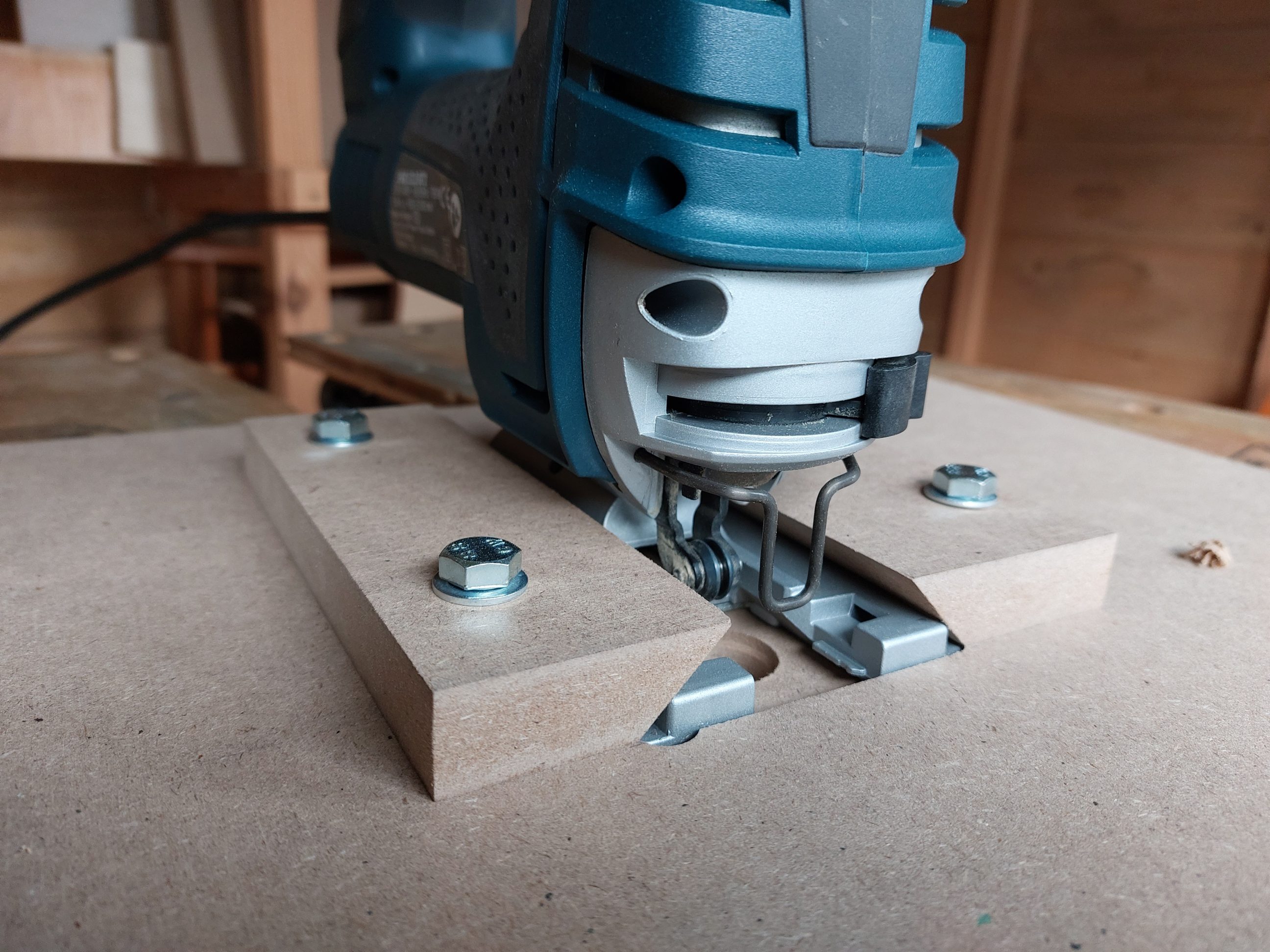
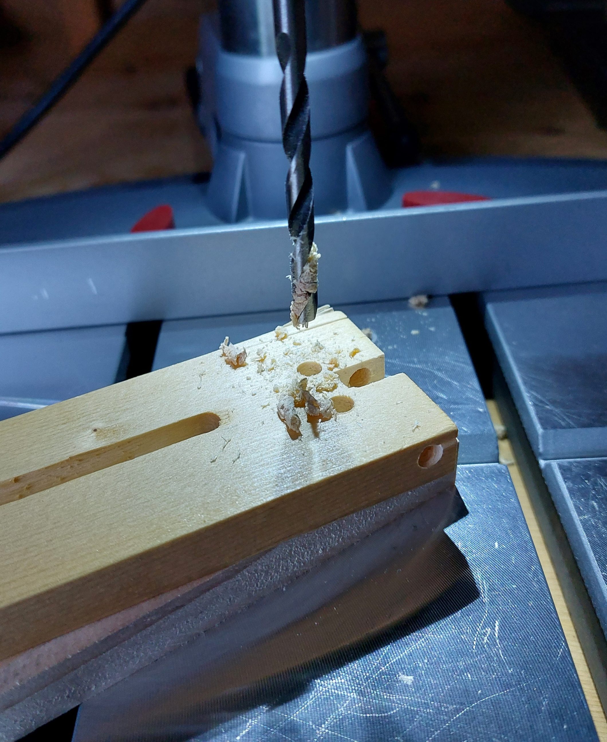
As I neared the end of the project, I still had to complete the 3-bearing blade support. The bearings I had ordered, described as 685zz and measuring 5 x 11 x 5 mm, required 5 mm bolts to secure them in place. I positioned the back support bearing lower and the 2 side bearings above it. During the drilling process, I made the mistake of not supporting the workpiece, which caused a blowout on the other side. To salvage the situation, I used a quick painter’s tape trick to complete the step, but I still had to glue all the chips back together. Learning from that experience, I applied masking tape from the bottom to cut the slot for the bearing, using the very jigsaw table that was still under construction.


There was a flaw, major this time, in that construction, something I didn’t predict – the blade could easily hit the bolt that held the vertical tab in place. I had to route out a shallow groove for the bolt head – I clamped a scrap block of wood in my workbench to elevate the workpiece which was fixed to the block with double-sided tape. That way I could easily use my router with a parallel guide. The guide was detached in the next step to finish off the corners free-hand. I also ground off the bolt head, just a bit, leaving a wide channel for the blade and still having some material to grab with a slotted screwdriver. In retrospect, I realize that grinding off the bolt was unnecessary and I erred on the side of caution. Despite this, I’m pleased with how the bolt sits flush with the tab and ensures no damage to the jig or blade.

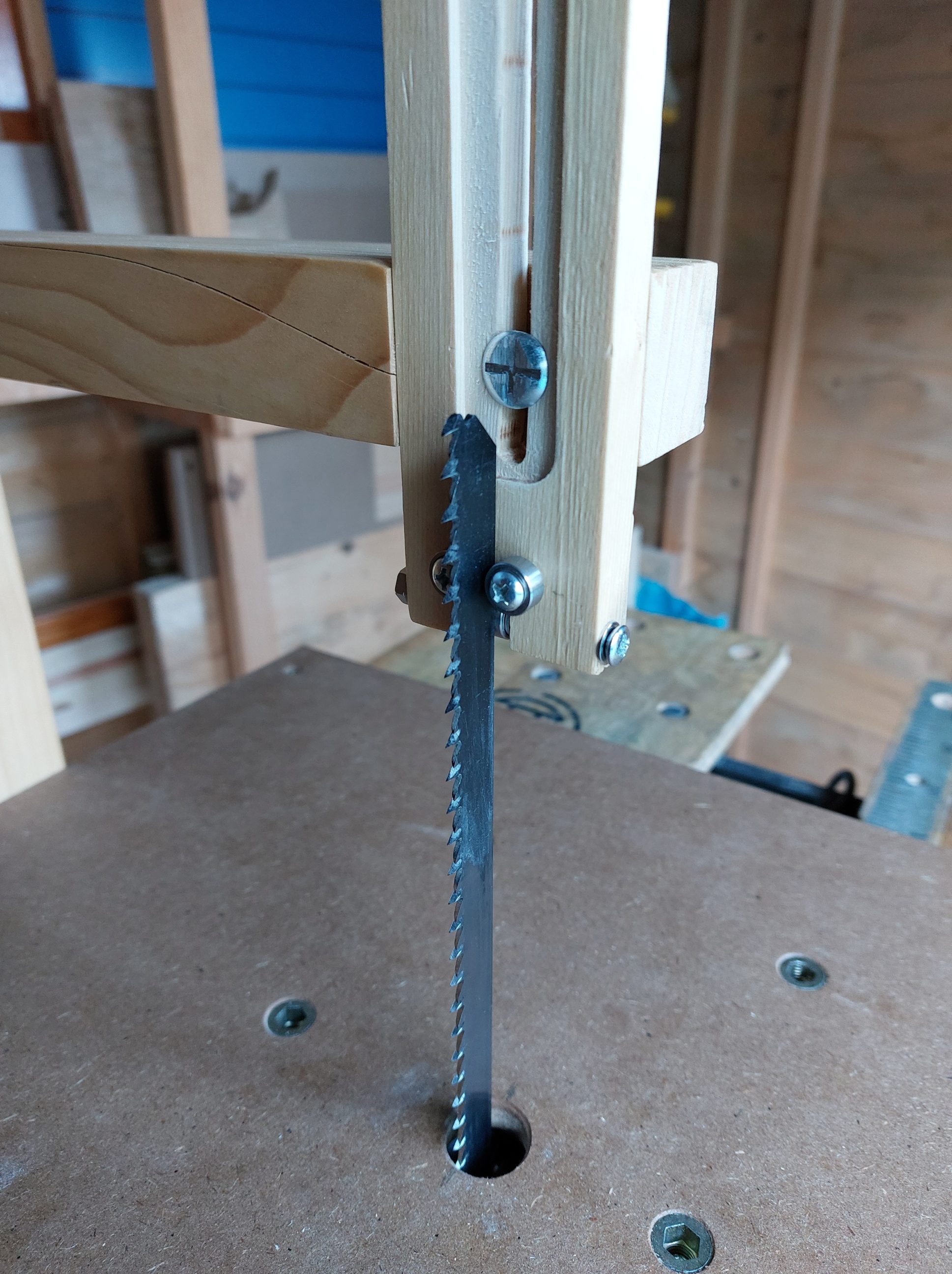


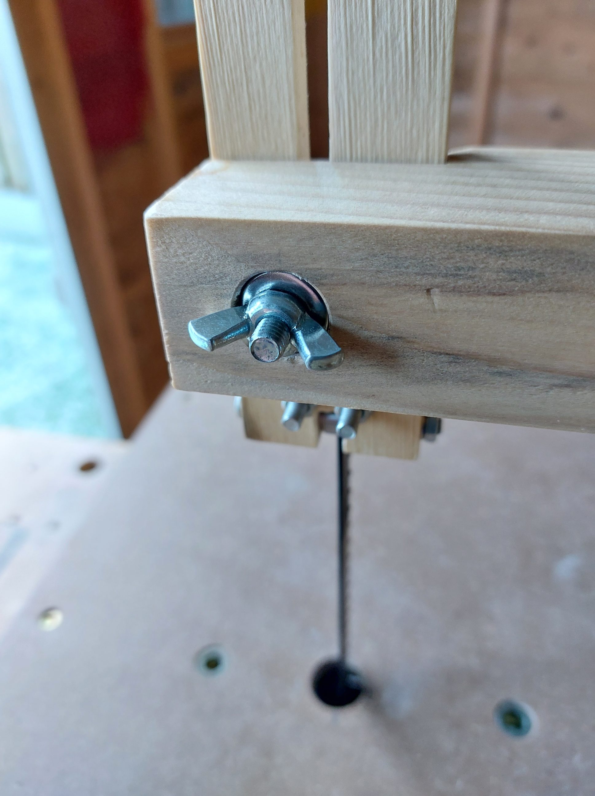
The back of the L-arm featured a deep nest for the bolt head, which was now on the wrong side. I filled up that nest with washers, including both regular and spring types so that I could use it with a wingnut easily. I also verified that the 3-bearing guide was functional, and it was; the blade had left some black protective paint on the bearings, demonstrating that it had used them as support. The final issue to address was the L-arm’s lower mounting point – I needed two bolts instead of just one to prevent the arm from tilting forward during use. I wanted to lower the arm anyways, I even drilled an additional hole and tested that height with the shorter blades. Now, I had two unsightly holes that needed to be concealed. I cut off the first one and covered the other with a t-lap joint.


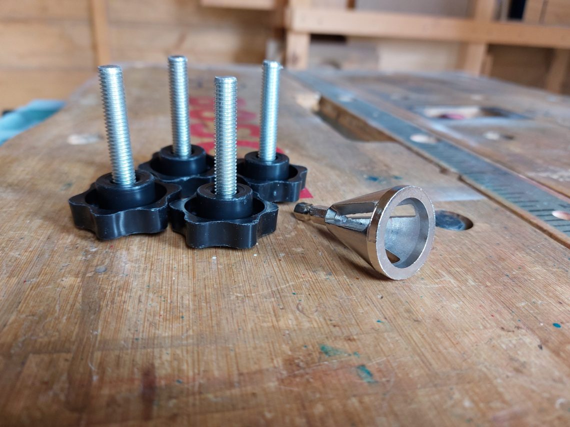
One of the runners was temporarily detached and got 2 new mounting points, instead of 1, equipped with inserts for a quick, one-handed assembly. I knew it was only a jig, but all the old holes were hidden from sight by the upgraded mechanism. I also installed spring washers to all 3 bolts holding the bearings – that way everything should stay in place, regardless of the vibrations. Some of these alterations and upgrades had to be sanded and refinished again, which was the last step in this project. I just wanted to make sure that the jig worked – every upgrade was tested straight away by making test cuts. Additionally, a smaller blade for cutting curves was ordered, as well as a set of fancy star head knobs. They were received in one size, but I trimmed and deburred them to fit my needs. I ended with 2 bolts of 8 x 35 and 4 bolts of 8 x 60 mm – for jigsaw clamping blocks and for the L-arm mounting foot.


Because this project was made over the wintery Christmas period, it all took a very long time to complete. The outside temperature was the 1st reason – glueing or finishing jobs couldn’t be done in low temperatures and the 2nd reason – all the online orders and their shipments were terribly delayed because of the holiday shutdowns. Some items were not available locally and had to be purchased internationally. Nonetheless, the jig was finally finished and tested. It can be used with or without the arm, it works perfectly with small and bigger workpieces. Easy to store and assemble, nicely built and finished – handy jig that was on my to-do list for a long time.