3 finger joint trays and 2 jigs
I wanted those trays to be made of wood, at least their frames. Solid wood looks better and is easier to sand. The material I had in stock required some work before use, it had to be ripped to thinner pieces and planed. But that wasn’t something I was afraid of – making the jigs and cutting the finger joints was the most interesting part of the process. That was due to the fact that for the first time, those joints were cut with a dado blade. Not only did I have to make a dedicated throat plate for my saw, but I also had to make a few box joint jigs. A lot was going on before the actual cuts were made.
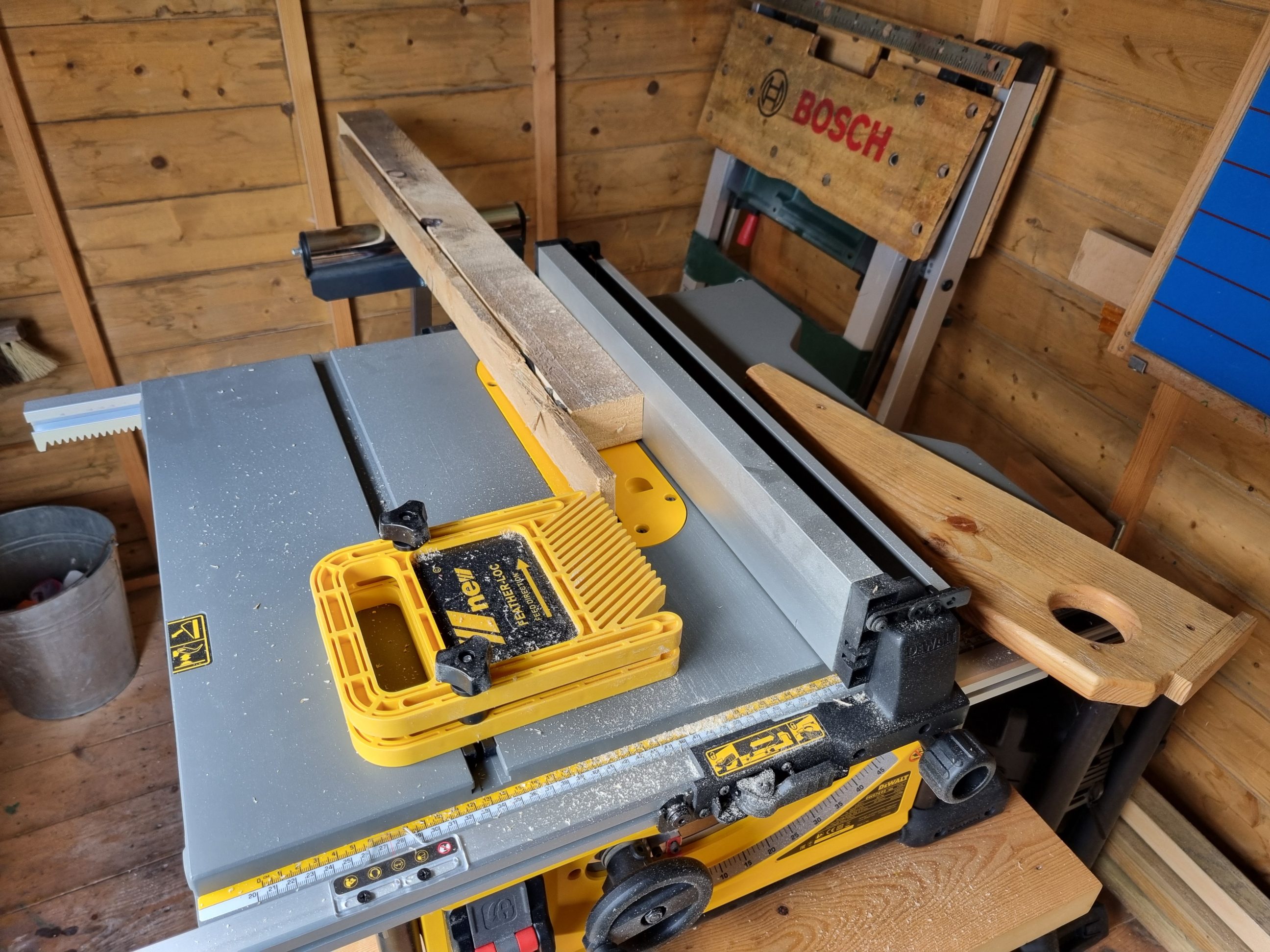
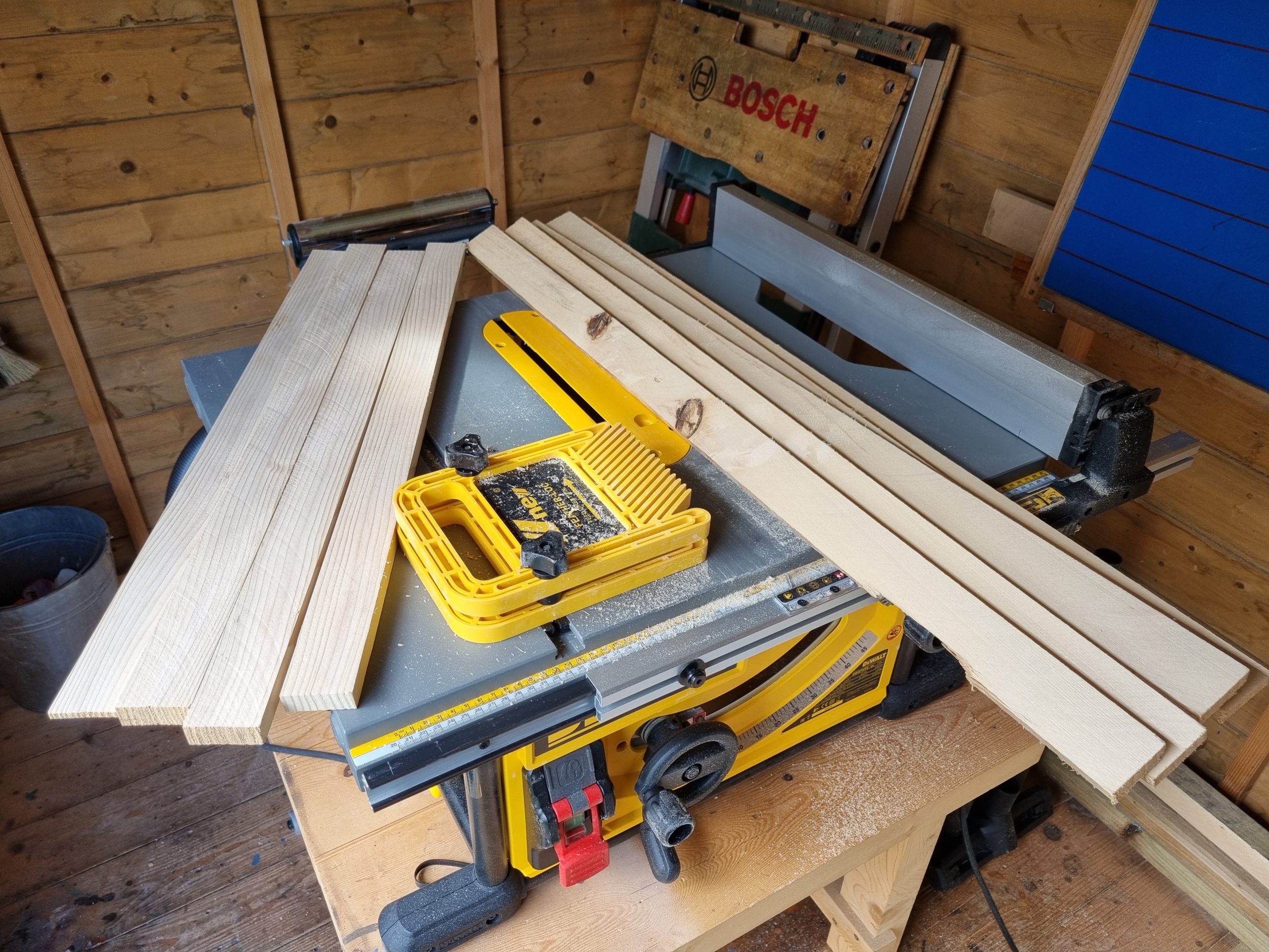

I began by rip-cutting two thick boards into thinner slats. I installed the correct blade and arranged two feather boards, one atop the other, to ensure the ripping process was both smooth and safe. Then, using my thickness planer, I processed the slats into two piles: one of 10 mm and the other of 15 mm thick material. I let them rest for a few days to release any moisture and acclimate. The most challenging part was making the first frame, as it was my initial experience with a dado stack. I started by cutting the sides of my first tray to the desired length. I then adjusted the mitre gauge fence to allow the blade to pass through. This fence has a notch that proves useful occasionally. It’s equipped with a set of 2 adjustable pins for cutting finger joints, but I opted to create my own box joint jig first, and then try those 2 pins. Using a piece of scrap plywood attached to the mitre gauge fence with clamps, I raised the blade to the appropriate height and made the initial cut.


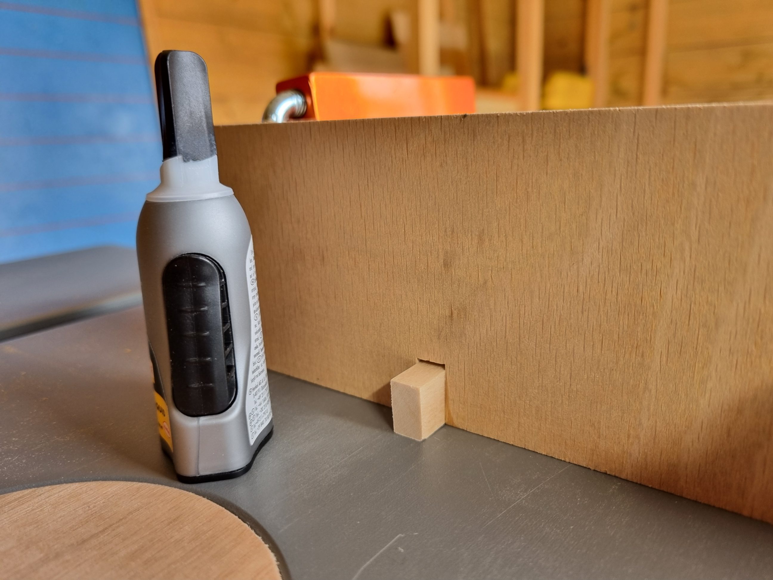
Next, I made the pin, as thick as the notch (blade). To achieve the correct thickness, I utilised my 12-volt planer set to zero, that way I removed tiny shavings and got the perfect fit. I cut the pin to size and glued it in place with super glue. The remaining piece of timber was used to set the pin (fence) at the right distance away from the blade.


All those 4 slats were cracked on one edge, and that crack was always oriented towards the pin. That process can be a little confusing, but with a simple mark on one edge is much easier. I used the natural marks occurring in wood and didn’t have to bother with making my own. But I did mark the outside corners with letters from A to D, to have a better understanding of what I was cutting and glueing together, later on in the process. The most confusing part was starting the following side, using the one cut previously as a spacer. Again, the correct orientation of the marks was the key. Plus, the starting cut on the following slat was always a full kerf cut, and not as I thought, a cut that would supplement the partially cut finger on the previous piece. The first cut on every side was always a full-width cut. In other words, I cut these joints in pairs, from A to D. The first cut on each pair was with the slat set against the pin (and its mark, a crack in my situation). Then it was flipped over, with the full-width finger facing against the pin and the other slat (of that pair) set against it. The process for the next pair started over.


I had to trim down all the sides of my first frame a few times during the process and ended up with a much smaller box than planned. That was a part and cost of my learning process. Nonetheless, I proceeded to a glue-up, when all 4 sides were cut. I made sure my clamps were equipped with soft foam stickers, to eliminate dents. The clamps were only used to bring the fingers together and removed straight away as they were bowing the sides. To make sure the frame was square I used the workbench dogs and tightened the two sides of it together. The glue was removed with a scraper after 15 minutes, when became a little gummy.


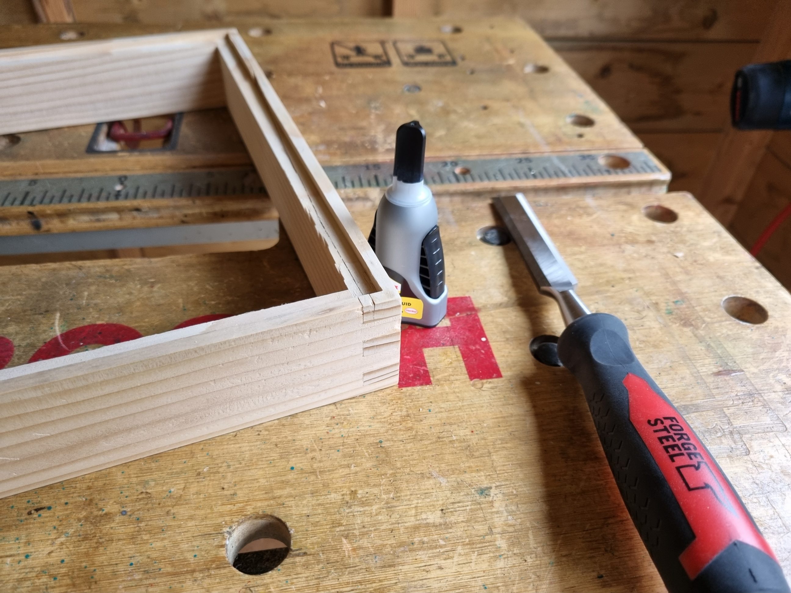
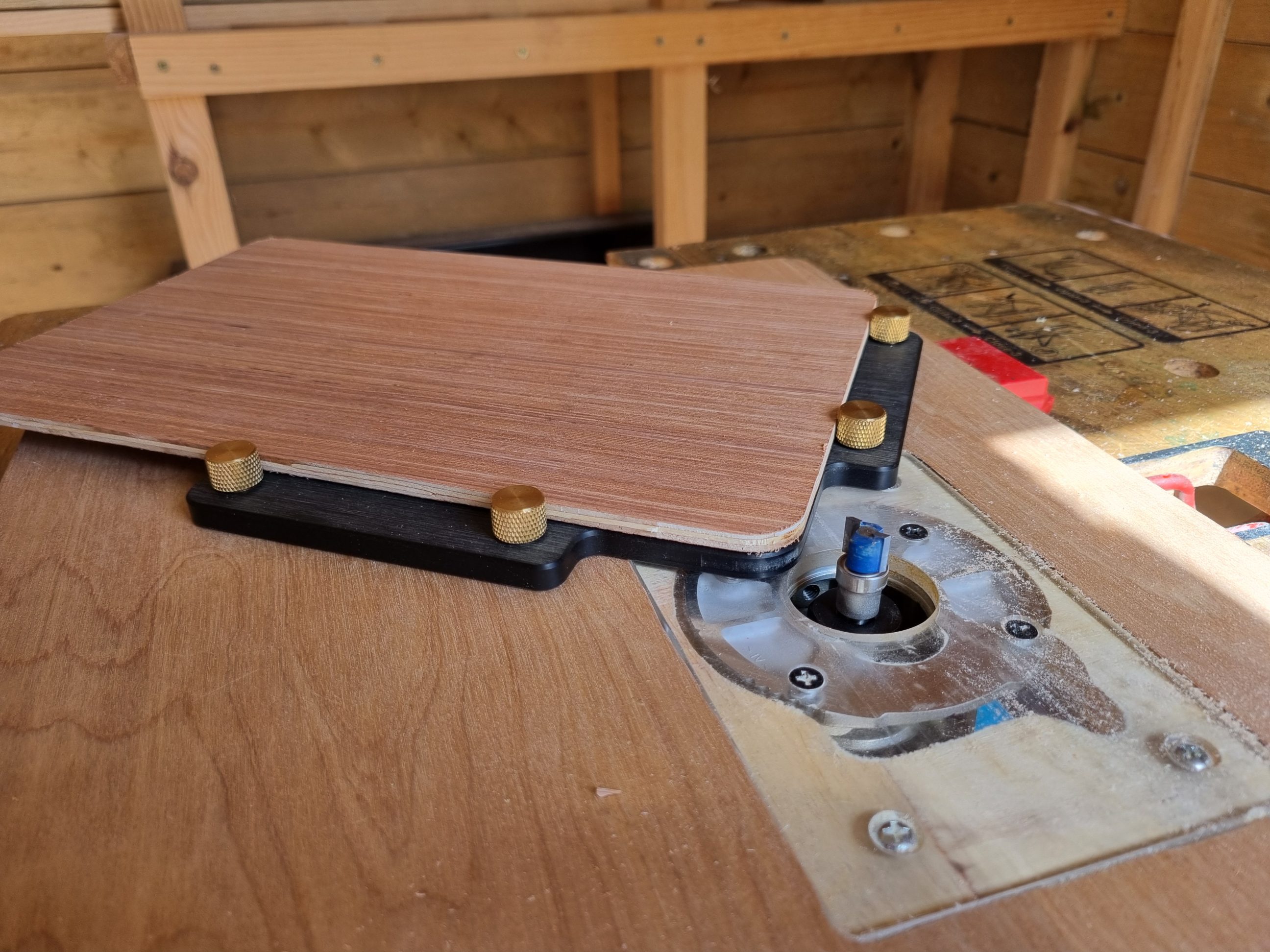
When the glue dried, I cut off the fingers flush using a chisel and then sanded the frame with my finishing sander. It took a lot of time and now I know that it would be much faster to use an oscillating belt sander for that task, or a flush-cut saw instead of a chisel. But as I mentioned earlier, that was my practice. Next, I set my router table and cut a rebate for the bottom panel. The corners were squared with a chisel. Some of the material chipped off and it had to be glued back with super glue.

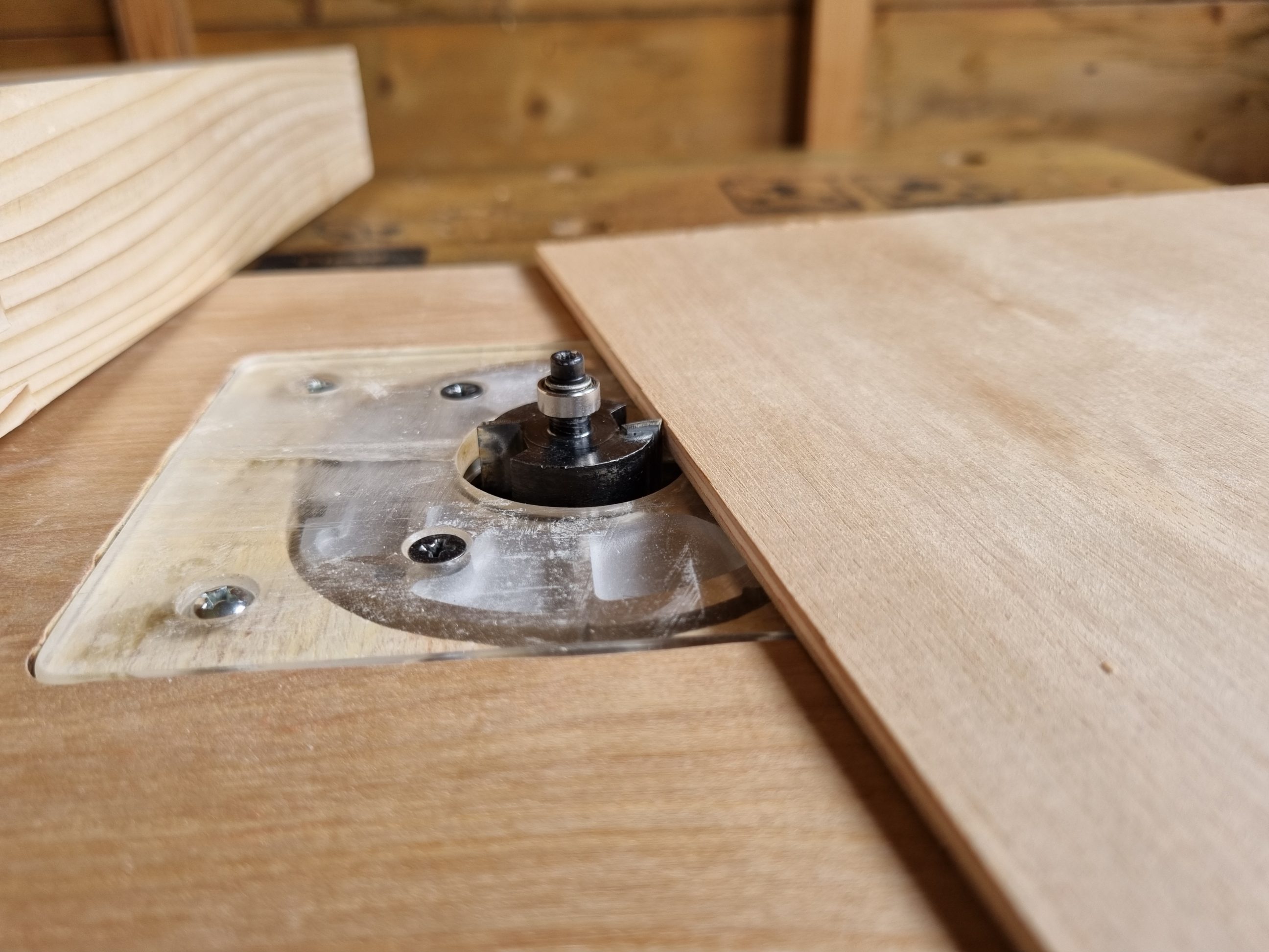


Once I knew the dimensions, I cut the plywood sheet to size and tacked it to the frame using brad nails. Since the sides were cracked on the bottom, they didn’t stand the routing step well and some of the wood was pulled out with the spinning router bit. I applied all-purpose filler to all the imperfections, cracks and nail holes that could be seen on the bottom. With a damp sponge, I next wiped the excess off, focusing on cleaning inside the grain of plywood. When it dried, it looked OK for a shop tray.


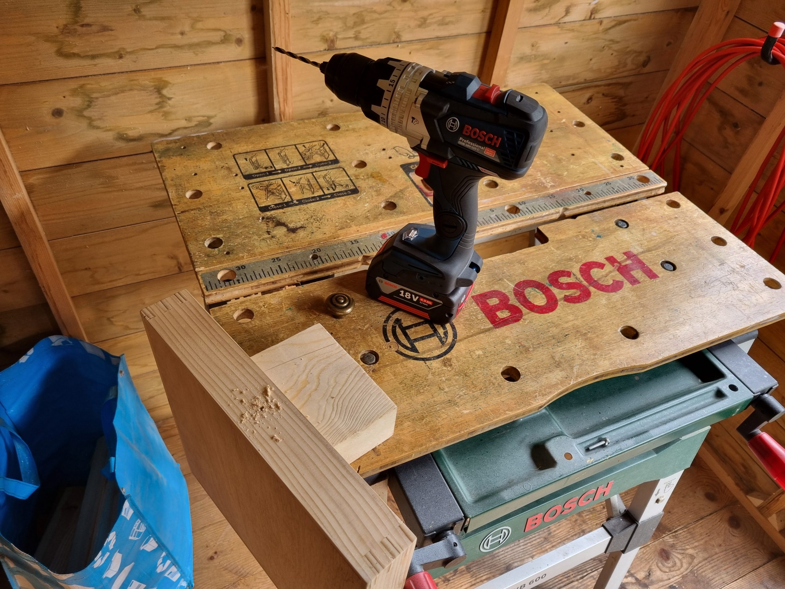
I drilled a hole for the knob and installed it in the front of the tray. As always, it was placed a few millimetres above the centre line, which usually looks better than perfectly centred. I knew that finishing all 3 trays at once would make more sense, so I put that tray aside and moved on with my work.

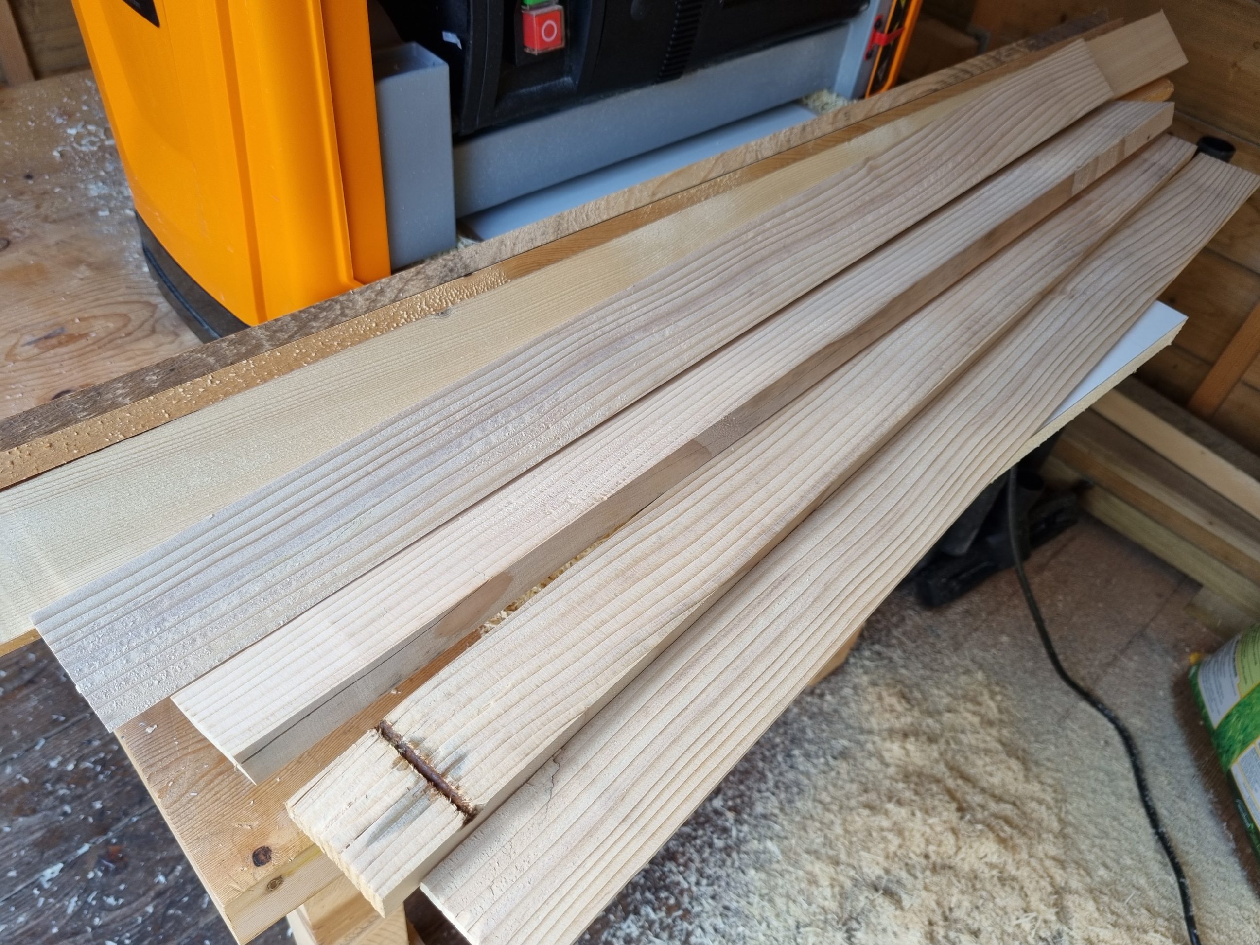
The next tray was made out of the finest timber. Originally it was a single board, 2.4 m long (8 feet) but for easier handling and storage, I cut it in half. It wasn’t hard to spot that those 2 halves were cupped when stored on top of the other. Thickness planing was the only option and with a few light passes I managed to remove the cup, still saving as much of their thickness as I could. They only shrank from 15 to 13 mm and that was perfect for the project.


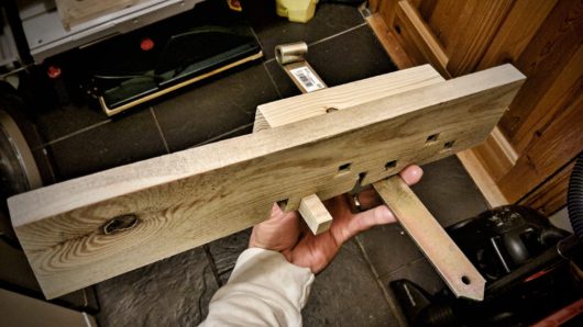
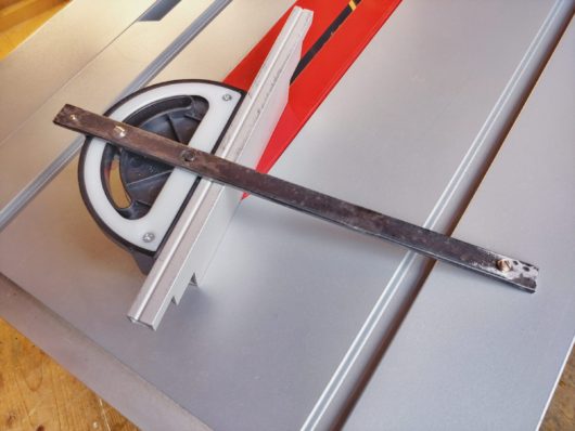
The edges were not square to the faces, so I trimmed them at a perfect 90º angle using my table saw and a feather board mounted before the blade. With that blade installed, I cut the sides of 2 trays to length and also prepared the backing plates for my second finger joint jig.


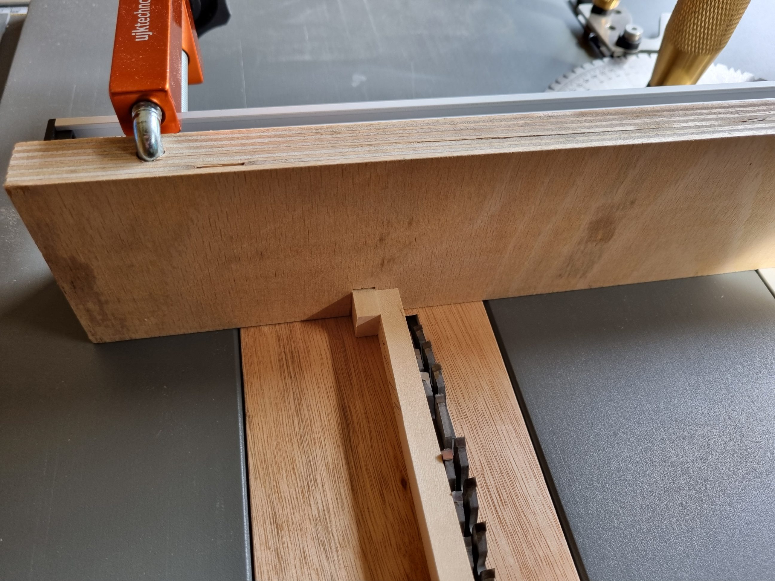
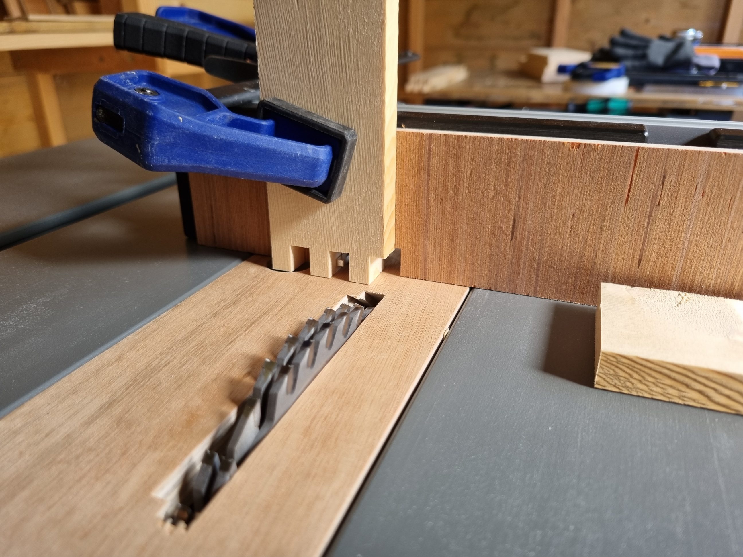
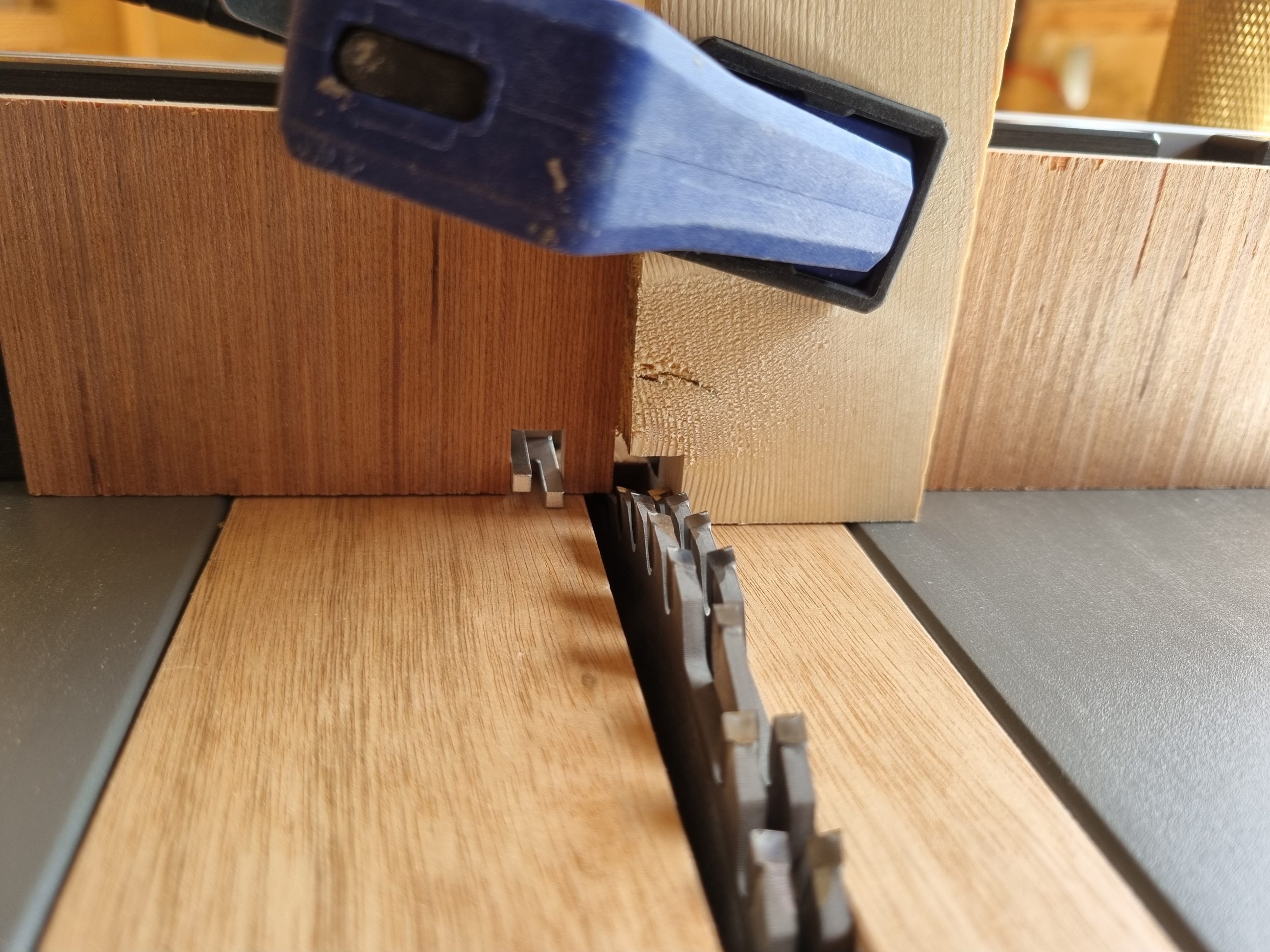
Since the homemade finger joint jig worked well, I still wanted to give the built-in one a shot. The only thing I didn’t like about it was the design of cutting through the vinyl backing as it was a sacrificial board. It was all explained in the instructions, so there was no way to use the jig differently … or was there? I had an idea! The thickness of my dado blade was 8.25 mm (21/64″). With a calliper locked at that size, I moved one of the pins away from the blade and set the other at the correct thickness. A very simple and effective way of setting everything up with just one tool. It worked perfectly on the first attempt! When it was all set up, I cut the notch on the plywood backing plate, using a scrap of wood as a spacer to keep the plywood before the pins but still parallel to the main fence. I then fixed it to the fence with double-sided tape, with way too much of it. It wasn’t easy to remove it afterwards.


The idea of saving the vinyl plate was partially successful. Due to the dado blade thickness, I only had to score the vinyl plate. If the blade was thinner I wouldn’t have to cut through it at all. Nonetheless, the damage was minimal and I was happy with it. I moved on to cutting the thinner pieces first and then raised the blade for the thicker material, the dado blade thickness remained the same for all 2, or actually 3 trays. I didn’t want to use clamps to hold the workpieces in place, but it was just out of my comfort zone. I didn’t feel comfortable with the blade that close to my hands. Using a quick-release clamp proved to be fast and effective, the cuts were probably even cleaner and more precise with it.


When all the pieces were cut, which didn’t take much time at all, I quickly dry-fitted them and glued them together. As like with the first tray, those two were initially squeezed together with clamps, to close the finger joints, but the clamps were removed right after that. It all stayed in place perfectly fine without any help, and it was square straight away. When the glue became gummy, I scraped off the excess using my stainless steel pry bar. It proved to be an excellent tool for the job as it reflected the light and helped to work inside darker corners with ease. I let the trays dry overnight and the next day I continued my work.


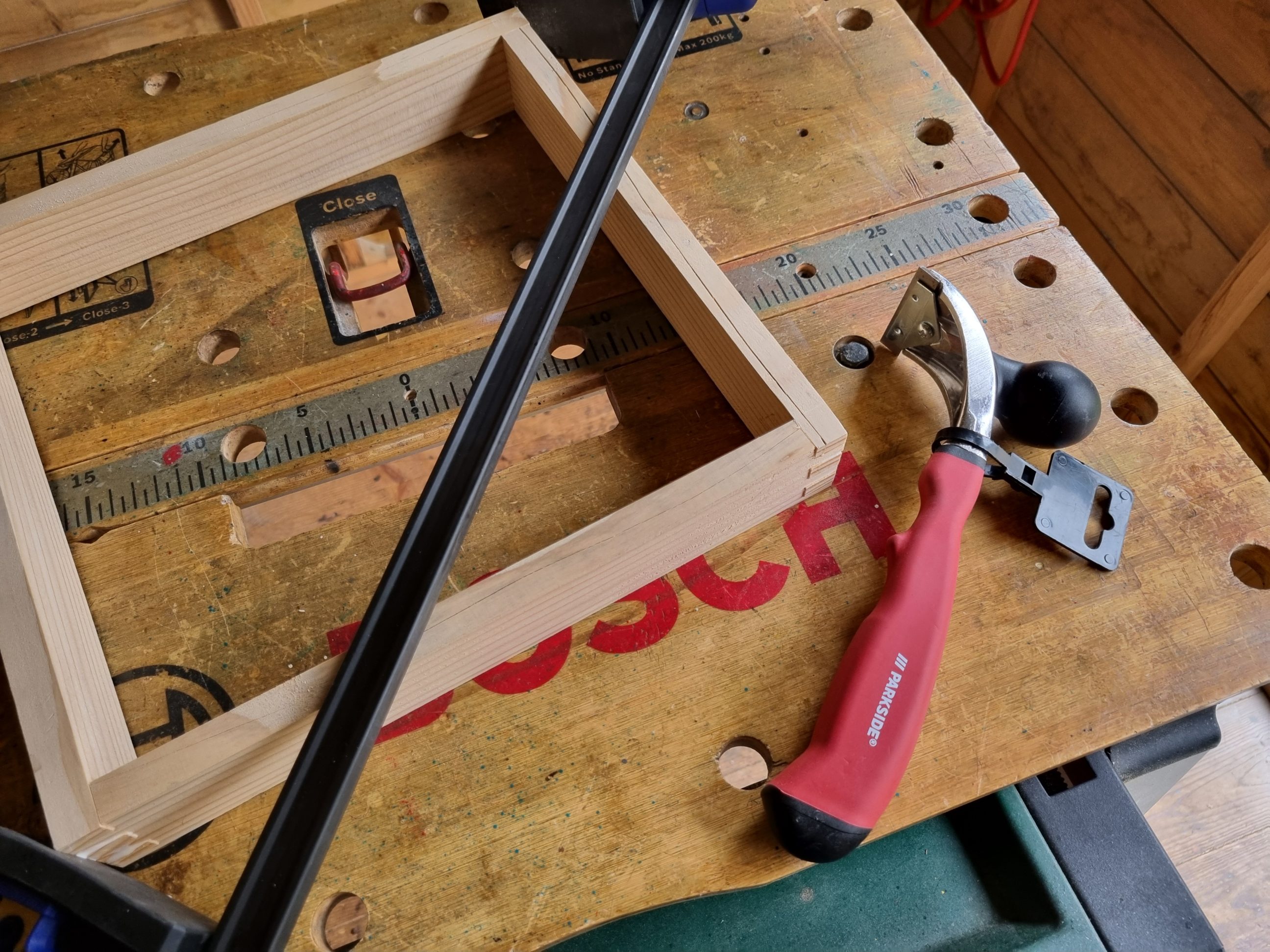
I purchased a pair of pull handles and installed them on trays #1 and #3. Tray #1 already had a knob, which I didn’t like, neither its placement nor its look. I took it out and filled the hole with filler, the handle was installed on the opposite side. Next, I routed out a rebate for the bottom, just in the taller tray. First, I scored a line with a marking gauge to minimise tear-out and then proceeded with the actual routing. That time I didn’t square off the corners to avoid any potential splitting. I sanded the inside edges with my oscillating tool and nailed the bottoms with my 18 gauge nailer. The lower tray got its bottom fixed straight to the edge of the frame, with a little overhang that was sanded flush later on in the process. I used my oscillating spindle sander for all 3 trays, even the first tray was sanded again, partially because of the filler job but also to get better results than with the last sanding. An oscillating spindle sander, or probably a belt sander too, seemed to be a perfect tool for the job – my finishing sander was too gentle and slow.


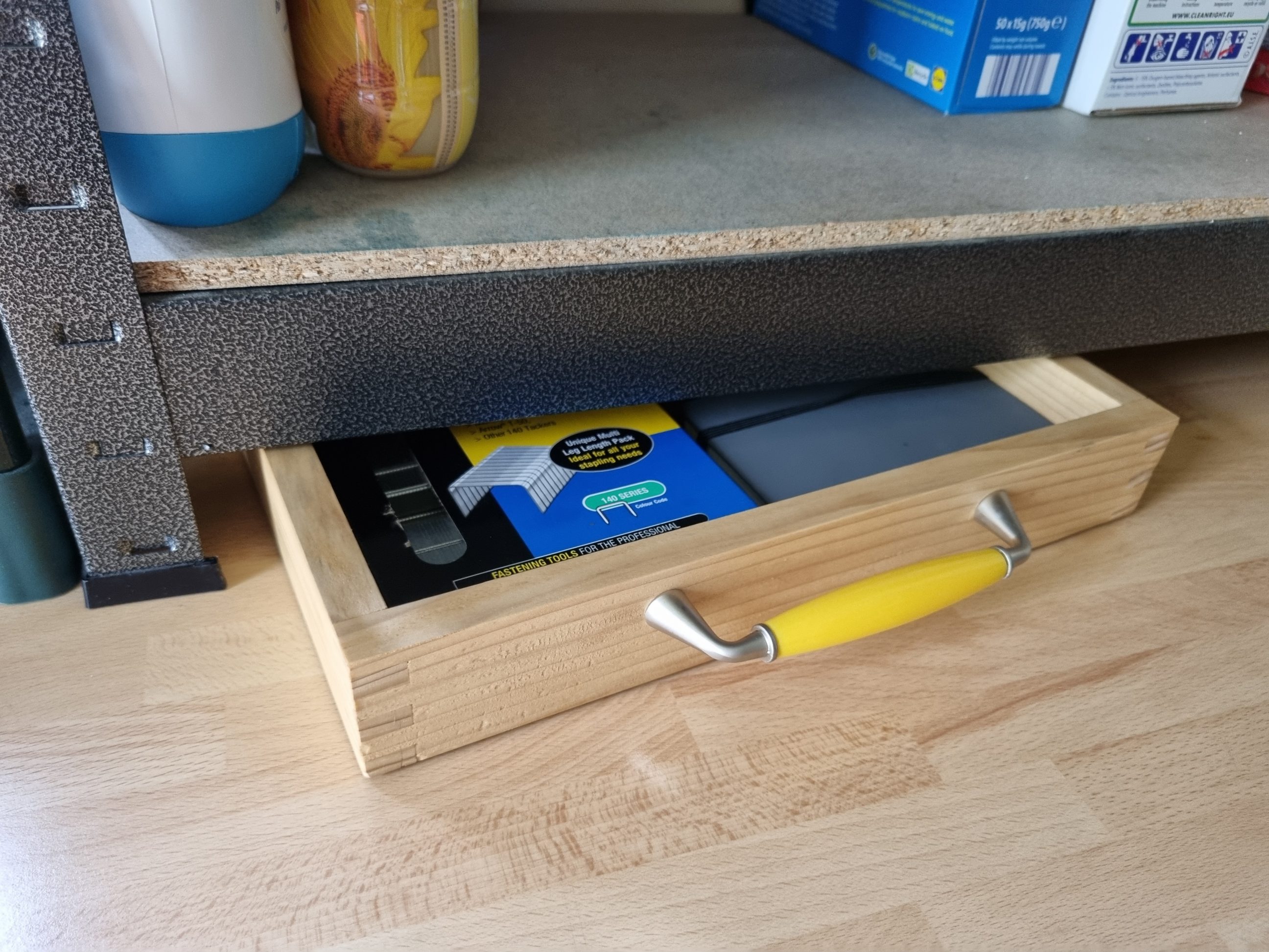
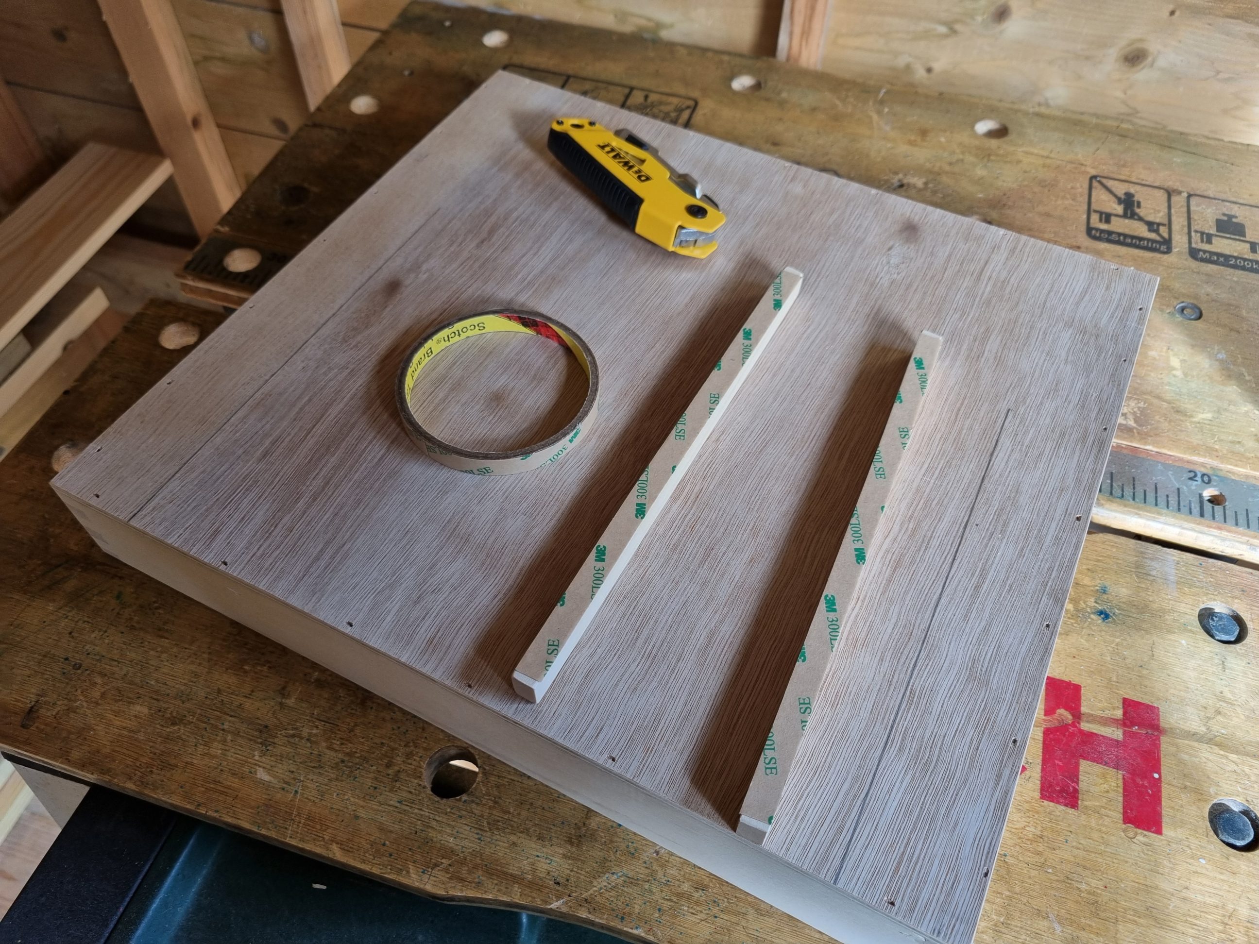
Next, I sanded all the arrises with a sanding block. It created nice-to-the-touch chamfers, that not only increased the durability of my trays, by minimising chipping and wear along the edges but also helped in the finishing process, by improving the flow and adhesion of hard wax oil around the arrises. For the battery tray (as I called it) I installed a pair of runners, using double-sided tape. When everything was prepared I moved on to applying the finish.


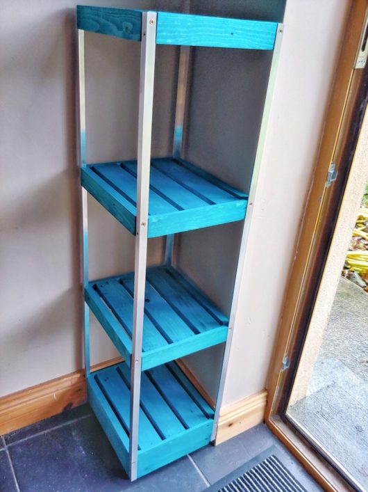
Two coats of hard wax oil were brushed onto the trays, which were then left to dry for several days. Once they were no longer tacky, I attached the handles using the predrilled holes. To protect surfaces during use, I affixed foam or felt pads to the backs or bottoms of the trays. That ensured the tallest tray sat flush with the shelf without hitting the wall, and the other tray did not touch the countertop directly. The battery tray was simply pushed into slots.

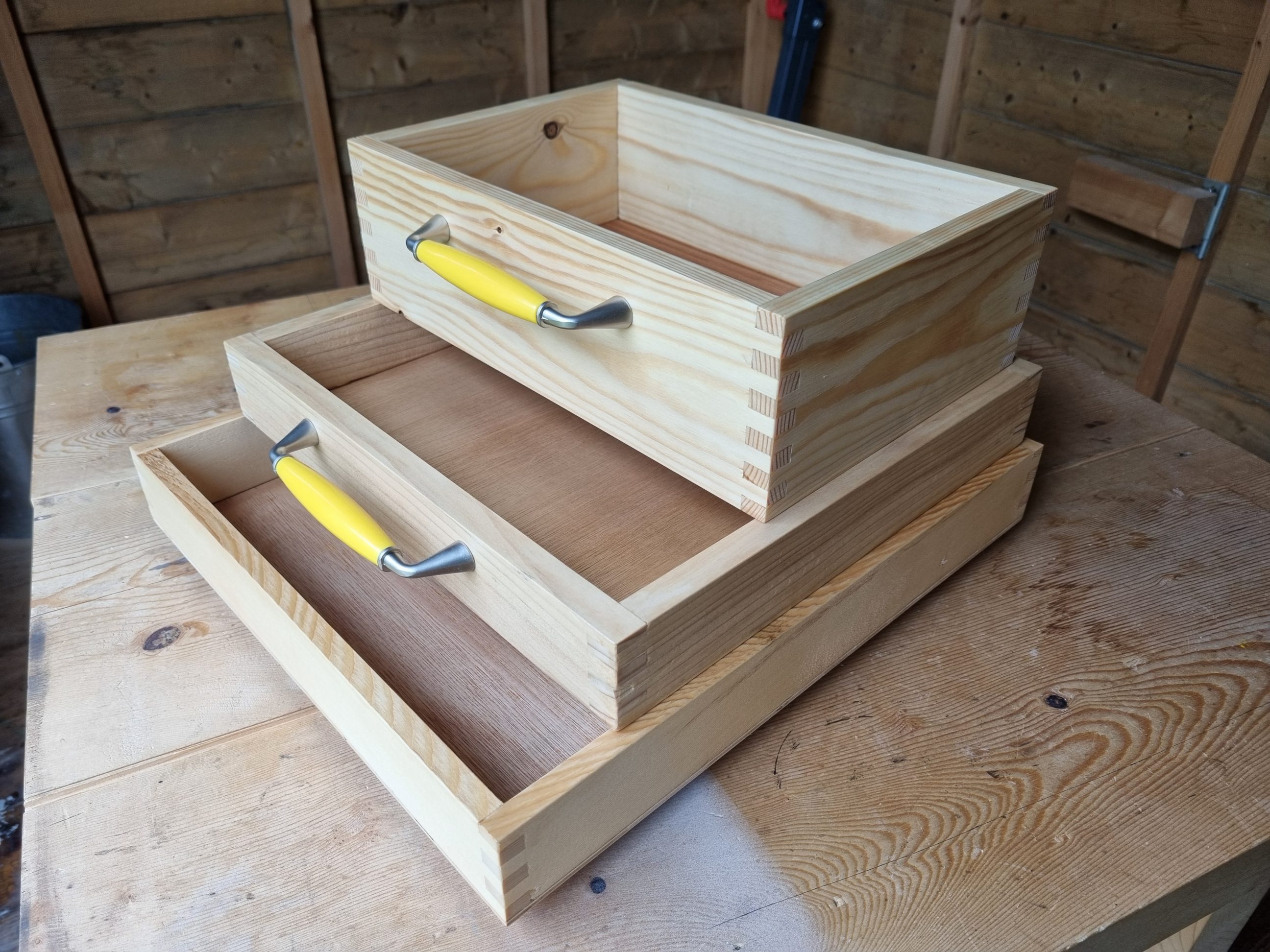


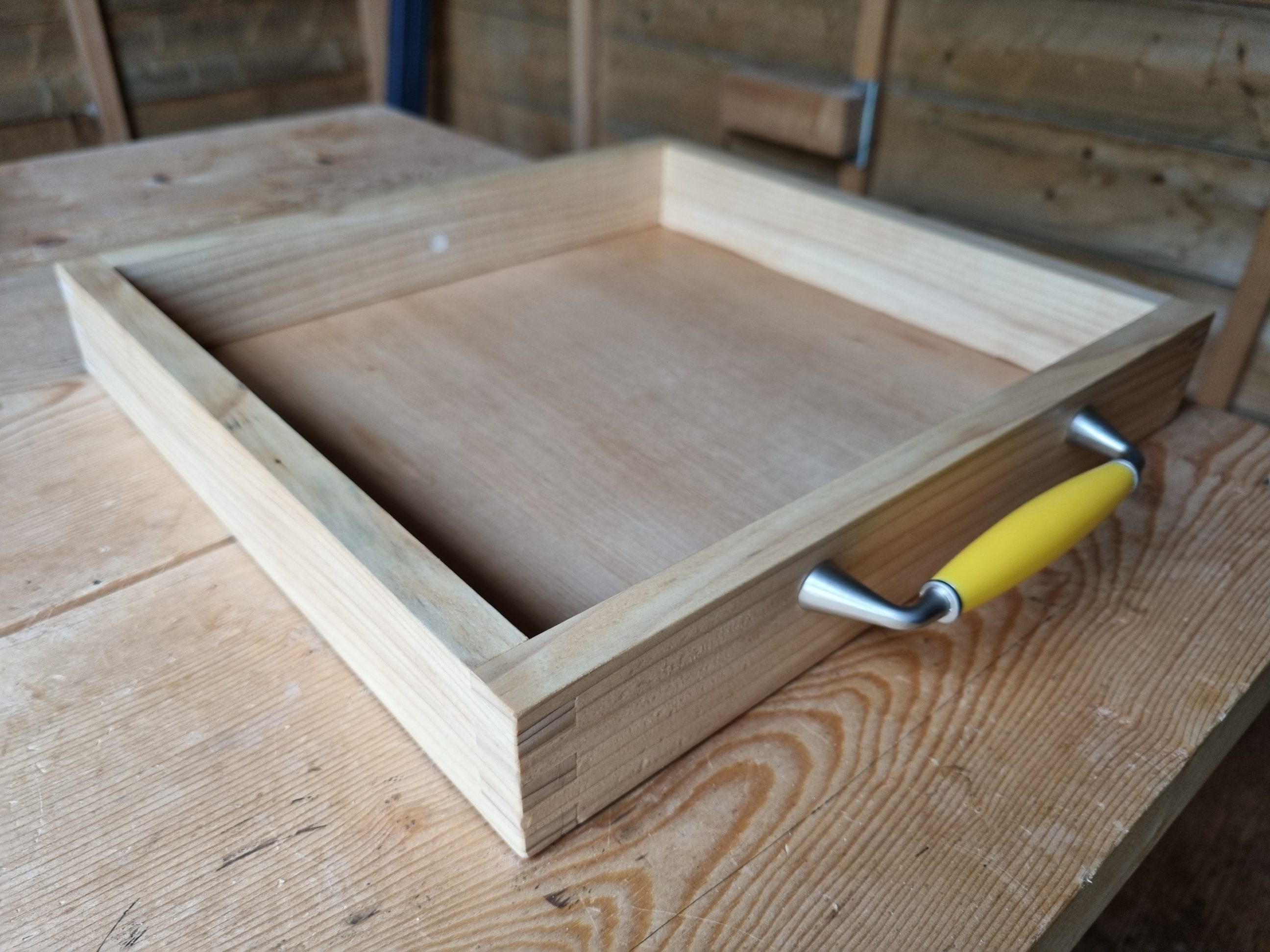


Everything was now organised, and the storage appeared more uniform. The joinery and finish were consistent across all trays, as were the handles. With each project, I discover new favourite techniques for woodworking and other DIY tasks. I’ve taken a liking to using finger joints, and I’ve mastered cutting and attaching plywood bottoms, as well as selecting the appropriate finishes – knowing which ones to avoid. Let me elaborate: creating a cut list for finger joint boxes is simple, requiring no calculations; you simply cut the wood to the length of your final product. The joints are both strong and aesthetically pleasing. They are compatible with thin materials; even 10 mm boards pose no issue – in fact, thinner materials enhance the appearance. For the bottoms, those with rounded corners are superior, eliminating the need for chiselling and the risk of chipping. For the most refined products, the bottoms may be glued to the frames, although securing them with 18 gauge nails is also effective. As with all my work, I build and I learn.